
Composite Building Blocks
A technology of building blocks and limit stops, which is applied in the direction of buildings, building components, building structures, etc., can solve the problems of fragile size, insufficient strength, and inability to change, and achieve the effect of small size and good flexibility
- Summary
- Abstract
- Description
- Claims
- Application Information
AI Technical Summary
Problems solved by technology
Method used
Image

Examples
Embodiment Construction
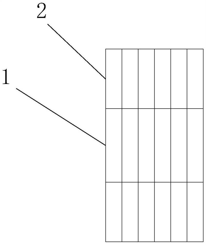
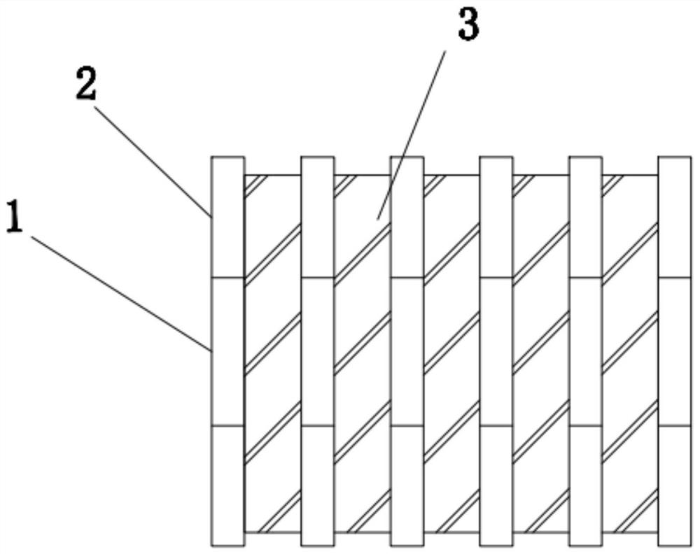
[0021] Such as figure 1 As shown, the composite building block includes more than one adjustable support ring, a rectangular filling cavity is formed in the middle of the support ring, and a filling film layer 3 with telescopic expansion ability is filled in the rectangular filling cavity, and the filling film layer 3 has an independent filling chamber 6, and the outer wall surface of the filling film layer 3 is in contact with the inner wall of the rectangular filling chamber;
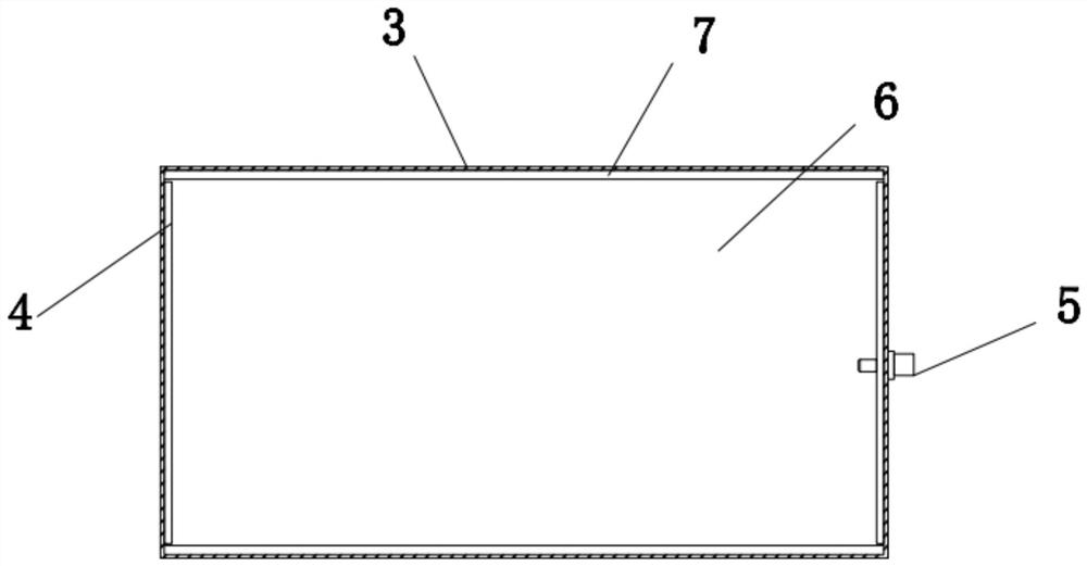
[0022] Such as figure 2 As shown, a first limiting rib 4 is provided on two opposite surfaces of the inner wall of the filling cavity 6 , and a second limiting rib 7 is respectively provided on the other two opposing surfaces of the inner wall of the filling cavity 6 .
[0023] Such as Image 6 As shown, the first limit rib 4 includes a middle part 71 and a rotating part 73 arranged on both sides of the middle part. An assembly cavity is respectively provided on both sides of the middle part 71, an...
PUM
 Abstract
Description
Claims
Application Information