ECU brushing tooling with clamping mechanism

A clamping mechanism and tooling technology, applied in the directions of collaborative operation devices, computer parts, software deployment, etc., can solve the problems of slow work rhythm, cumbersome ECU flashing tooling operation, and more labor consumption, so as to achieve convenient tool replacement. Effect

Pending Publication Date: 2019-08-23
FAW CAR CO LTD
View PDF0 Cites 0 Cited by
  • Summary
  • Abstract
  • Description
  • Claims
  • Application Information

AI Technical Summary

Problems solved by technology

[0003] The existing ECU flashing tooling is cumbersome to operate. Manual insertion and extraction are required for ECU flashing. The work cycle is slow, and more manpower is required for batch operations.

Method used


Image

  • ECU brushing tooling with clamping mechanism
  • ECU brushing tooling with clamping mechanism
  • ECU brushing tooling with clamping mechanism

Examples


Embodiment Construction

[0018] In describing the present invention, it should be understood that the terms "upper", "lower", "front", "rear", "left", "right", "top", "bottom", "inner", " The orientation or positional relationship indicated by "outside", etc. is based on the orientation or positional relationship shown in the drawings, and is only for the convenience of describing the present invention and simplifying the description, rather than indicating or implying that the referred device or element must have a specific orientation, so as to Specific orientation configurations and operations, therefore, are not to be construed as limitations on the invention.

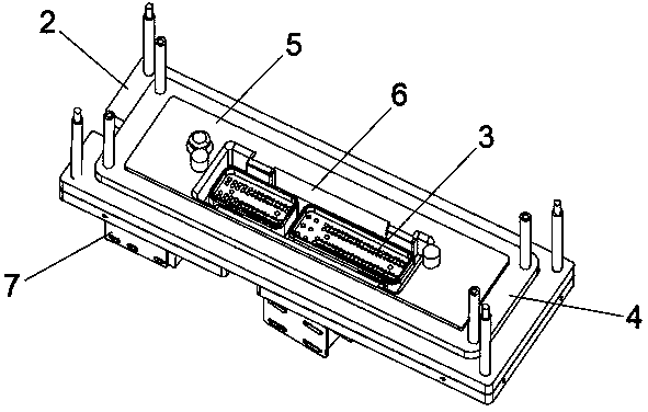
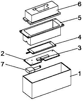
[0019] see figure 1 , figure 2 and image 3 As shown, an ECU flashing tool with a clamping mechanism includes a tooling bottom case 1, a needle plate assembly 2 is fixedly installed on the tooling bottom case 1, and a slot 3 is provided on the needle plate assembly 2, and the slot 3 There is a test probe inside, which can pop up automa...


PUM


Abstract

The invention discloses an ECU brushing tooling with a clamping mechanism, and the tooling comprises a tooling bottom shell fixedly mounted with a needle plate assembly, wherein the needle plate assembly is provided with a slot, the upper end of the needle plate assembly is further fixedly connected with a tooling support plate and a light plate, the light plate is located below the tooling support plate, a light guide groove is fixedly inserted in the tooling support plate, the slot is located inside the groove body of the light guide groove, and the lower end of the needle plate assembly ismounted with a buckle assembly. The ECU brushing tooling provided by the invention can help the staff to more easily judge the remaining brushing time and display the current working state more intuitively by cooperating with the ECU brushing tooling by setting a light plate of a plurality of colors and a plurality of flashing ways, and realizes the automatic locking and pop-up action of the ECU with more convenient tooling replacement by setting the slot and detecting probe cooperated with the main electromagnet, sub-electromagnet and hook of the buckle assembly.

Description

technical field [0001] The invention relates to the technical field of ECU flashing tooling, in particular to an ECU flashing tooling with a clamping mechanism. Background technique [0002] ECU electronic control unit, also known as driving computer and on-board computer, is a microcomputer controller dedicated to automobiles in terms of use. With the popularization of automobiles in China, ECU flashing and diagnosis in vehicle maintenance have been widely used. [0003] The existing ECU flashing tooling is cumbersome to operate. It needs to be manually inserted and pulled out when performing ECU flashing. [0004] For this reason, we propose an ECU flashing tool with a clamping mechanism. Contents of the invention [0005] The purpose of the present invention is to solve the problems in the background technology, and propose a kind of ECU flashing tool with clamping mechanism. [0006] In order to achieve the above object, the present invention adopts the following tec...

Claims


Application Information

Patent Timeline
IPC IPC(8): G05B23/02G06F8/61G06K17/00
CPCG05B23/0221G06F8/61G06K17/0025
Inventor 张海龙朱海龙
Owner FAW CAR CO LTD
Why Eureka
Try Eureka