Wireless charging coil

A wireless charging and coil technology, applied in the direction of transformer/inductor coil/winding/connection, circuit, inductor, etc., can solve the problems of poor practicability and low wireless charging efficiency, and achieve the effect of improving practicability

Pending Publication Date: 2019-08-30
XJ POWER CO LTD +1
View PDF0 Cites 4 Cited by
  • Summary
  • Abstract
  • Description
  • Claims
  • Application Information

AI Technical Summary

Problems solved by technology

[0004] The purpose of the present invention is to provide a wireless charging coil for solving the...

Method used


Image

  • Wireless charging coil
  • Wireless charging coil
  • Wireless charging coil

Examples


Embodiment 1

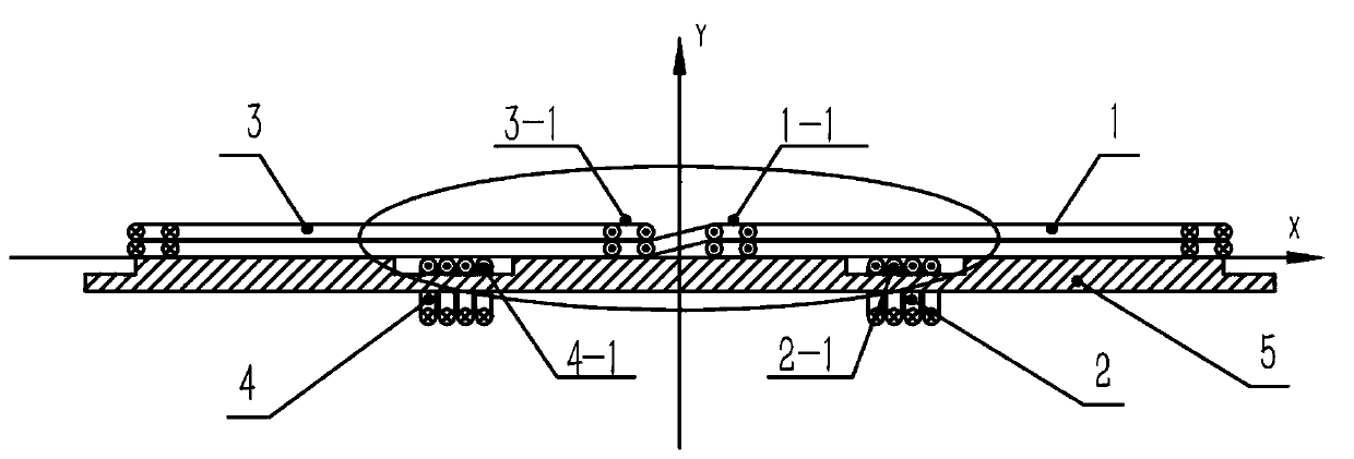
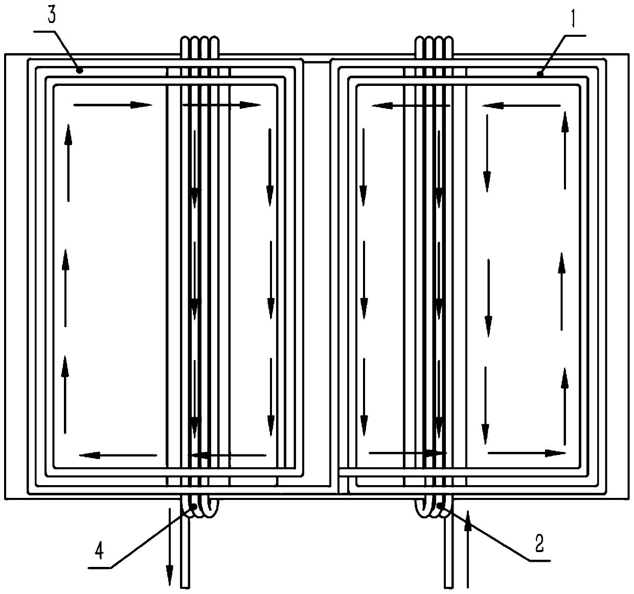
[0023] Such as figure 1 The shown wireless charging coil includes an excitation layer 5, and a first coil loop loop 1, a second coil loop loop 2, a third coil loop loop 3, and a fourth coil loop loop wound by the same insulated wire. 4. In order to describe the positional relationship of the four coil loops, in figure 1 The coordinate system is drawn with the vertical line of the excitation layer as the y-axis and the horizontal direction along the excitation layer as the x-axis.

[0024] Such as figure 1 As shown, the four coil loops are respectively located in four quadrants, and the winding shapes are all rectangular. Wherein, the first coil loop 1 and the third coil loop 3 are adjacently arranged on the upper end surface of the excitation layer 5 , and the planes of the first coil loop 1 and the third coil loop 3 are parallel to the excitation layer 5 .

[0025] The second coil loop loop 2 is adjacent to the fourth coil loop loop loop 4, and is arranged around the uppe...

Embodiment 2

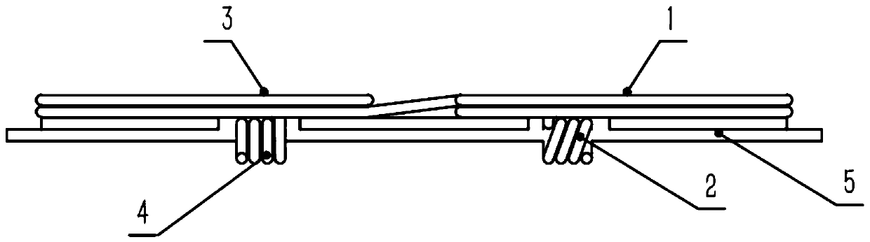
[0034] The wireless charging coil of this embodiment is as Figure 5 , Image 6 As shown, it includes an excitation layer 5 and a coil loop loop wound by the same insulated wire. The coil loop loop includes a first coil loop loop 1 and a second coil loop loop 2, wherein the first coil loop loop 1 is arranged in the excitation On the upper end face of the layer, the plane where the first coil loop loop 1 is located is parallel to the excitation layer 5 .

[0035] The second coil loop 2 surrounds the upper and lower end surfaces and two side surfaces of the excitation layer 5; The current direction of -1 is consistent, and the side 2-1 of the second coil loop on the upper end surface of the excitation layer is set close to the side 1-1 of the first coil loop. The upper end surface of the excitation layer 5 is provided with a groove, and when the number of coil turns of the second coil loop 2 is multiple turns, the insulated wire of the second coil loop 2 is placed in the groov...


PUM


Abstract

The invention relates to a wireless charging coil, and belongs to the technical field of wireless charging. The wireless charging coil comprises an excitation layer and coil annular loops wound by thesame insulating wire, wherein the coil annular loops includes a first coil annular loop and a second coil annular loop, the first coil annular loop is arranged on the upper end face of the excitationlayer, and the plane where the first coil annular loop is located is parallel to the excitation layer; and the second coil annular loop is arranged around the upper and lower end faces and two side surfaces of the excitation layer. The two coil annular loops are designed by using the same insulating wire, so that the magnetic field generated by the wireless charging coil after being electrified is enabled to be strengthened. Compared with the wireless charging coil in which the same insulating wire only forms one coil annular loop in the prior art, the excitation effect is enhanced, and the wireless charging efficiency and the practicability of the charging coil are improved.

Description

technical field [0001] The invention belongs to the technical field of wireless charging, and in particular relates to a wireless charging coil. Background technique [0002] With the development of modern society, electronic equipment is constantly updated, and people put forward higher requirements for the performance and functions of electronic equipment. The traditional charging method brings a lot of inconvenience to people's life when it is used, and the wireless charging method has emerged as the times require, which solves the inconvenience caused by the traditional charging method using charging wires. The wireless charging method is mainly based on the principle of electromagnetic induction. It is convenient and fast without the need for charging wires to contact the mobile phone device. However, the disadvantage is that the charging efficiency is lower than the traditional wired charging method. How to improve the charging efficiency is a difficult problem in wire...

Claims


Application Information

Patent Timeline
IPC IPC(8): H01F27/24H01F27/28H01F27/30H01F38/14H02J50/10
CPCH01F27/24H01F27/2823H01F27/306H01F38/14H02J50/10
Inventor 朱传涛甘江华吕劲松陈天锦李建国宋兵兵张晓丽刘振威赵钊渠边慧萍
Owner XJ POWER CO LTD
Why Eureka
Try Eureka