High-power synchronous rectification high-frequency switching power supply

A technology of high-frequency switching power supply and synchronous rectification, which is applied in the direction of converting AC power input to DC power output, output power conversion device, electrical components, etc. Problems such as transformer heat dissipation effect, to achieve good heat dissipation effect, avoid complex cooling circuit, and compact structure

Pending Publication Date: 2019-09-03
洪道绿
View PDF1 Cites 2 Cited by
  • Summary
  • Abstract
  • Description
  • Claims
  • Application Information

AI Technical Summary

Problems solved by technology

[0006] However, the above assembly structure of high-power synchronous rectification high-frequency switching power supply has at least the following defects: 1) Two conductive double-hole busbars are arranged in parallel, and the transformer is arranged between the two conductive double-hole busbars, thus reducing the Heat dissipation effect; 2) The transformer of the above-mentioned switching power supply is arranged between two conductive double-hole busbars, and other components are arranged on the two conductive double-hole busbars, which forms an overall sandwich structure. The frequency of maintenance is relatively high, and the disassembly of the sandwich structure is cumbersome during maintenance, so it is not convenient for maintenance work and assembly activities

Method used


Image

  • High-power synchronous rectification high-frequency switching power supply
  • High-power synchronous rectification high-frequency switching power supply
  • High-power synchronous rectification high-frequency switching power supply

Examples


Embodiment Construction

[0043] The present invention will be described in further detail below in conjunction with the embodiments and accompanying drawings, so that those skilled in the art can implement it with reference to the description.

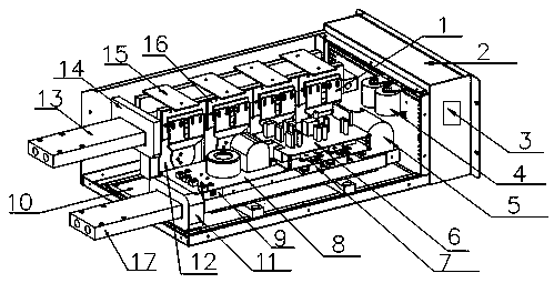
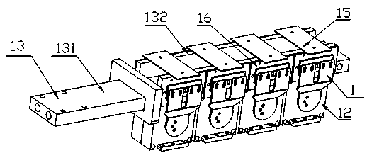
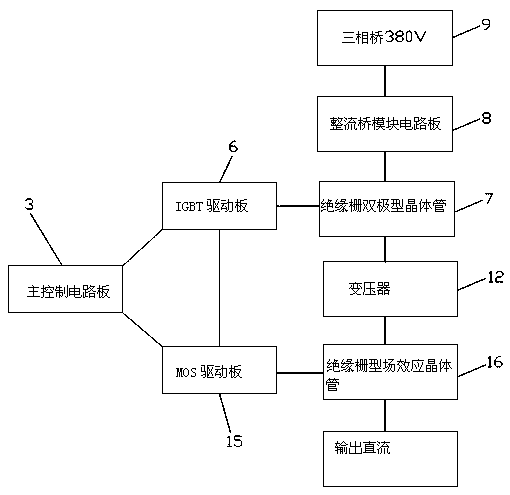
[0044] see Figure 1-2As shown, the embodiment of the present invention discloses a high-power synchronous rectification high-frequency switching power supply, including a conductive bar 1, a chassis 2, a main control circuit 3, a filter capacitor 4, a primary inductor 5, a chopper module (IGBT drive board 6, Insulated gate bipolar transistor 7), rectifier bridge module circuit board 8 (abbreviated as plate), three-phase input rectifier stack 9, connecting aluminum plate 10, reactor 11, transformer 12, first conductive busbar 13, current sensor 14, The second rectifier module (MOS transistor driver board 15, MOS transistor 16) and the second conductive busbar 17, wherein the insulated gate bipolar transistor 7 is connected to the IGBT driver board 6 for signal...


PUM


Abstract

The invention discloses a high-power synchronous rectification high-frequency switching power supply. The high-power synchronous rectification high-frequency switching power supply comprises a case, afirst conductive busbar, a second conductive busbar, transformers, a main control circuit, a three-phase input rectifier stack, a rectifier bridge module circuit board, a chopping module and a secondrectifier module. The first conductive busbar is positioned at the upper portion of the second conductive busbar, the first conductive busbar and the second conductive busbar are inserted in the casein parallel and in a staggered manner, one end of a conductive double-hole busbar is connected with the main control circuit, the other end of the conductive double-hole busbar extends out of the case, the transformers are fixedly arranged at the lower portion of the first conductive busbar in the extension direction of the first conductive busbar, the second rectifier module is arranged on the first conductive busbar and the transformers, and the chopping module, the three-phase input rectifier stack and the rectifier bridge module circuit board are arranged on the second conductive busbar.The switch power supply provided by the invention has the advantages of simple and reasonable arrangement of all parts, a compact structure, convenience in installation, disassembly and maintenance and good heat dissipation effect.

Description

technical field [0001] The invention relates to the technical field of power supply devices, in particular to a high-power synchronous rectification high-frequency switching power supply. Background technique [0002] At present, with the rapid development of power electronics technology, the relationship between power electronic equipment and people's work and life is becoming increasingly close, and electronic equipment cannot do without a reliable power supply. Because the high-frequency switching power supply has the advantages of small size, light weight and high efficiency compared with the traditional power frequency DC power supply, it has been widely used in high-current electrolysis, electrochemical and other occasions. [0003] At present, the known high-frequency switching power supply high-frequency transformer assembly structure is composed of a transformer, a circuit module, a Schottky tube or a rectifier diode after the transformer and a rectification part. ...

Claims


Application Information

Patent Timeline
Patent Type & Authority Applications(China)
IPC IPC(8): H02M7/00H02M7/219H05K7/20
CPCH02M7/003H02M7/219H05K7/2089H02M7/2195
Inventor 洪道绿
Owner 洪道绿
Why Eureka
Try Eureka