Method and device for determining image time stamp

A technology for determining methods and time stamps, applied in image communication, color TV parts, TV system parts, etc., to achieve the effect of improving accuracy

Active Publication Date: 2021-08-24
MOMENTA SUZHOU TECH CO LTD
View PDF6 Cites 0 Cited by
  • Summary
  • Abstract
  • Description
  • Claims
  • Application Information

AI Technical Summary

Problems solved by technology

However, because the exposure time of image imaging is not fixed, it will be different due to the external environment, such as the intensity of light, so the accuracy of the image time stamp obtained by this compensation method needs to be improved.

Method used


Image

  • Method and device for determining image time stamp
  • Method and device for determining image time stamp
  • Method and device for determining image time stamp

Examples


Embodiment 1

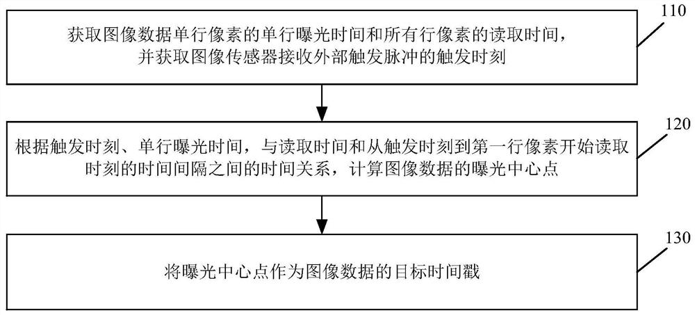
[0077] see Figure 1a , Figure 1a is a schematic flowchart of a method for determining an image time stamp provided by an embodiment of the present invention. The method is applied in automatic driving, and can be executed by a device for determining the time stamp of an image. The device can be realized by means of software and / or hardware, and generally can be integrated in a vehicle-mounted computer such as a vehicle-mounted computer or a vehicle-mounted industrial personal computer (Industrial personalComputer, IPC). In the terminal, the embodiments of the present invention are not limited. like Figure 1a As shown, the method provided in this embodiment specifically includes:

[0078] 110. Acquire the exposure time of a single row of pixels in a single row of image data and the reading time of pixels in all rows, and obtain the trigger moment when the image sensor receives an external trigger pulse.

[0079] In this embodiment, the image sensor may be a rolling shutter ...

Embodiment 2

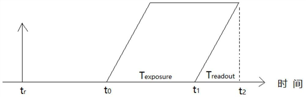
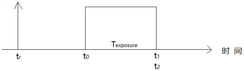
[0095] see Figure 2a , Figure 2a is a schematic flowchart of a method for determining an image time stamp provided by an embodiment of the present invention. This embodiment is optimized on the basis of the above embodiments, and is mainly applied to image acquisition that can obtain the first reading start time corresponding to the first row of pixels in the image data or the second reading end time corresponding to the last row of pixels device. For these image acquisition devices, the first reading start time and the second reading end time can be used as the image time stamps to be calibrated, and the real single-line exposure time can be used to compensate, and the real exposure center point of the image data can be obtained as the post-calibration The image timestamp. like Figure 2a As shown, the method includes:

[0096] 210. Acquire the exposure time of a single row of pixels in a single row of image data and the reading time of pixels in all rows.

[0097] 22...

Embodiment 3

[0109] see image 3 , image 3 It is a schematic structural diagram of an apparatus for determining an image time stamp provided by an embodiment of the present invention. like image 3 As shown, the device includes: a trigger moment acquisition module 310, an exposure center point calculation module 320 and a target time stamp determination module 330, wherein,

[0110] The trigger moment obtaining module 310 is configured to obtain the exposure time of a single row of pixels of the image data and the reading time of all rows of pixels, and obtain the trigger moment when the image sensor receives an external trigger pulse;

[0111] The exposure center point calculation module 320 is configured to be based on the trigger moment, the single-row exposure time, and the time between the read time and the time interval from the trigger moment to the first row of pixels to start reading relation;

[0112] The target time stamp determination module 330 is configured to use the ex...


PUM


Abstract

The embodiment of the present invention discloses a method and device for determining an image time stamp. The method includes: obtaining the exposure time of a single row of pixels in a single row of image data and the reading time of all pixels in a row, and obtaining the trigger moment when the image sensor receives an external trigger pulse ; According to the time relationship between the trigger moment, the single-row exposure time, and the read time and the time interval from the trigger moment to the first row of pixels starting to read the moment; the exposure center point is used as Destination timestamp for image data. By adopting the above technical solution, it is possible to obtain accurate image time stamps without using other sensor information.

Description

technical field [0001] The invention relates to the technical field of automatic driving, in particular to a method and device for determining an image time stamp. Background technique [0002] In autonomous driving and assisted driving systems, vehicles sense the world around them through sensors. Among many kinds of sensors, vision sensor is a very important sensory sensor. The video signal is collected by the visual sensor and transmitted to the vehicle computing and decision-making unit through GMSL (gigabit multimedia serial link), FPDLINK (video serial communication) and other media. One of the most important points is that it is necessary to obtain the precise moment when each frame of image actually occurs, so that the vehicle computing decision-making unit can fuse information from other sensors and make accurate judgments and decisions. [0003] The existing technology generally records the time when the image acquisition terminal receives the image frame data, a...

Claims


Application Information

Patent Timeline
Patent Type & Authority Patents(China)
IPC IPC(8): H04N5/235
CPCH04N23/73H04N23/74
Inventor 余振华
Owner MOMENTA SUZHOU TECH CO LTD
Why Eureka
Try Eureka