A leak-proof diaphragm pump

A diaphragm pump and diaphragm technology, applied in pumps, pump control, pump testing, etc.

Active Publication Date: 2020-12-25
NINGBO JLT ELECTRIC CO LTD
View PDF6 Cites 0 Cited by
  • Summary
  • Abstract
  • Description
  • Claims
  • Application Information

AI Technical Summary

Problems solved by technology

[0004] In view of the above-mentioned problems existing in the prior art, it is now intended to provide a leak-proof diaphragm pump in which a double-layer diaphragm is provided, and at the same time, a liquid detection device is arranged at the bottom of the outer diaphragm of the double-layer diaphragm, and the double-layer diaphragm The length of the outer diaphragm is longer than the length of the inner diaphragm. In addition, a rotating shaft with a first eccentric wheel and a second eccentric wheel is provided, and the degree of eccentricity of the second eccentric wheel relative to the rotating shaft is greater than that of the first eccentric wheel relative to the rotating shaft Under normal circumstances, the first eccentric wheel drives the inner diaphragm to move to realize pumping, but after the inner diaphragm is damaged, part of the fluid leaks into the outer diaphragm and is detected by the liquid detection device and an alarm is issued At the same time, after moving the rotating shaft, the second eccentric wheel with a greater degree of eccentricity is matched with the connecting rod of the diaphragm, which offsets the longer part of the outer diaphragm compared with the length of the inner diaphragm, so that the outer diaphragm can act as Temporarily use the diaphragm to realize the pump liquid, which can not only realize leakage prevention, avoid safety risks, ensure the performance of the pump liquid, but also facilitate the user to obtain damage information to achieve the purpose of timely maintenance, so that the equipment has an alternative structure after damage, It avoids the problem of inconvenient use caused by untimely maintenance after damage, and the use guarantee is higher

Method used


Image

  • A leak-proof diaphragm pump
  • A leak-proof diaphragm pump
  • A leak-proof diaphragm pump

Examples


Embodiment Construction

[0024] In order to make it easy to understand the technical means, creative features, goals and effects achieved by the present invention, the following examples are combined with the appended figure 1 to attach Figure 4 The technical solutions provided by the present invention are described in detail, but the following content is not intended as a limitation of the present invention.

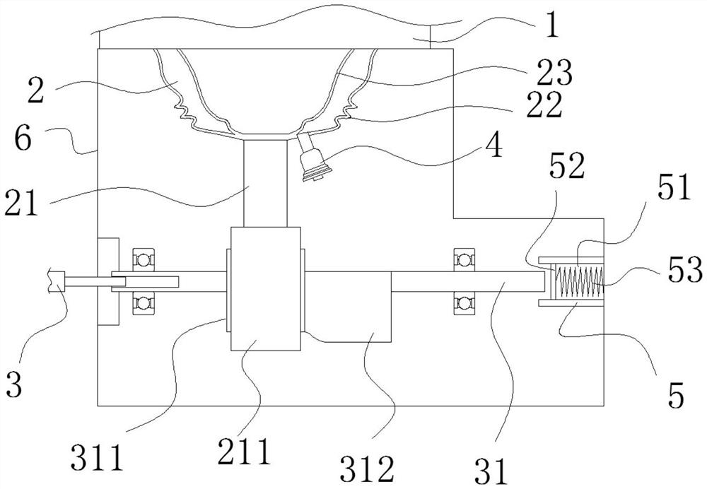
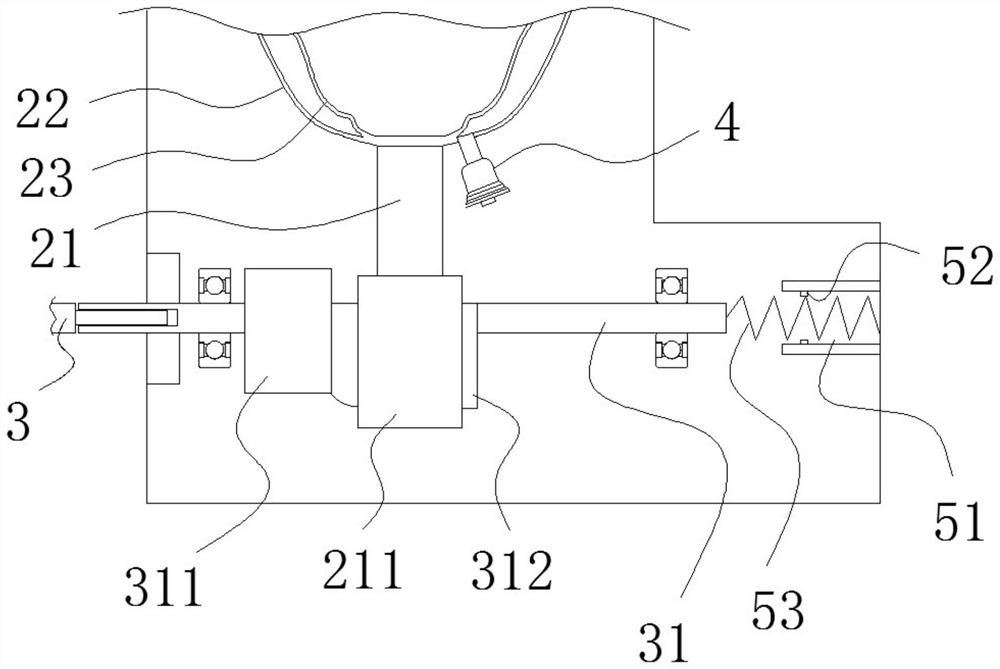
[0025] figure 1 It is a structural diagram of an embodiment of a leak-proof diaphragm pump of the present invention; figure 2 It is a structural diagram of the outer diaphragm of a preferred embodiment of the present invention during operation. Such as figure 1 with figure 2 As shown, the leak-proof diaphragm pump provided in this embodiment includes: a pump body 1, a diaphragm 2, and a drive assembly 3. The diaphragm 2 is arranged in the pump chamber of the pump body 1, and the drive assembly 3 is indirectly connected to the diaphragm 2 through a power transmission structure. On the co...


PUM


Abstract

The invention provides a leakage-proof diaphragm pump, and belongs to the technical field of diaphragm pumps. The leakage-proof diaphragm pump comprises a pump body, a diaphragm and a driving assembly, the diaphragm is arranged in a double-layer mode, the wall body of the outer-layer diaphragm is arranged in a folded mode, the inner-layer diaphragm is arranged in a diaphragm cavity of the outer-layer diaphragm and is connected with a connecting rod with a sleeve ring, the sleeve ring is arranged on a rotating shaft with a first eccentric wheel and a second eccentric wheel and can be horizontally moved, the second eccentric wheel is larger than the eccentric distance of the first eccentric wheel, the bottom of the outer-layer diaphragm is provided with a liquid detection device, so that theinner-layer diaphragm is damaged, and after the liquid detection device detects leakage, the rotating shaft is moved horizontally, so that the sleeve ring is matched with the second eccentric wheel with larger eccentric distance, so that the folded wall body of the outer-layer diaphragm is straightened, so that the diaphragm cavity of the outer-layer diaphragm can be deformed to serve as a temporary pump-liquid structure for replacing the inner-layer diaphragm, the problem that the use is inconvenient due to the fact that the maintenance is not timely due to damage is avoided, and the use guarantee is improved.

Description

technical field [0001] The invention relates to the technical field of diaphragm pumps, in particular to a leak-proof diaphragm pump. Background technique [0002] In some small water-using equipment such as coffee machines, diaphragm pumps are generally used to pump water, so the utilization rate of diaphragm pumps is getting higher and higher. [0003] At present, diaphragm pumps on the market include a pump body and a drive assembly. The pump body is provided with an inlet, a pump chamber, an outlet, and a bypass check valve with a pressure regulating device. Drive the movement of the diaphragm. The diaphragm includes a diaphragm cavity and a connecting rod. The diaphragm cavity is deformed through the lifting and lowering of the connecting rod to realize the change of the volume of the diaphragm cavity, so as to realize the operation of sucking the fluid from the inlet and discharging it from the outlet, realizing the operation of the diaphragm pump fluid. However, the...

Claims


Application Information

Patent Timeline
Patent Type & Authority Patents(China)
IPC IPC(8): F04B43/02F04B51/00F04B49/06
CPCF04B43/009F04B43/02F04B51/00
Inventor 刘光跃邵军钰王天龙高立
Owner NINGBO JLT ELECTRIC CO LTD
Why Eureka
Try Eureka