Lift-pressed outlet device

A technology of a water trap and a lifting body, which is applied to water supply devices, indoor sanitary piping devices, household appliances, etc., can solve the problems of failure of the lifting mechanism, small contact surface, and difficult cleaning of dirt such as hair, etc., and achieves cleaning of dirt. The effect of convenience and large lifting range

Inactive Publication Date: 2006-12-27
李荣春 +1
View PDF1 Cites 0 Cited by
  • Summary
  • Abstract
  • Description
  • Claims
  • Application Information

AI Technical Summary

Problems solved by technology

The inventor has previously designed a sanitary ware drainer (ZL01254544.9) with an elastic lifting mechanism. In this mechanism, a pull hook moves in the groove. Since the pull hook is made of rigid material, the contact surface in the groove is small. It is easy to flatten the curved surface in the groove and cause the lifting mechanism to fail; and there are also defects such as hair and other dirt that are not easy to clean

Method used


Image

  • Lift-pressed outlet device
  • Lift-pressed outlet device
  • Lift-pressed outlet device

Examples


Embodiment Construction

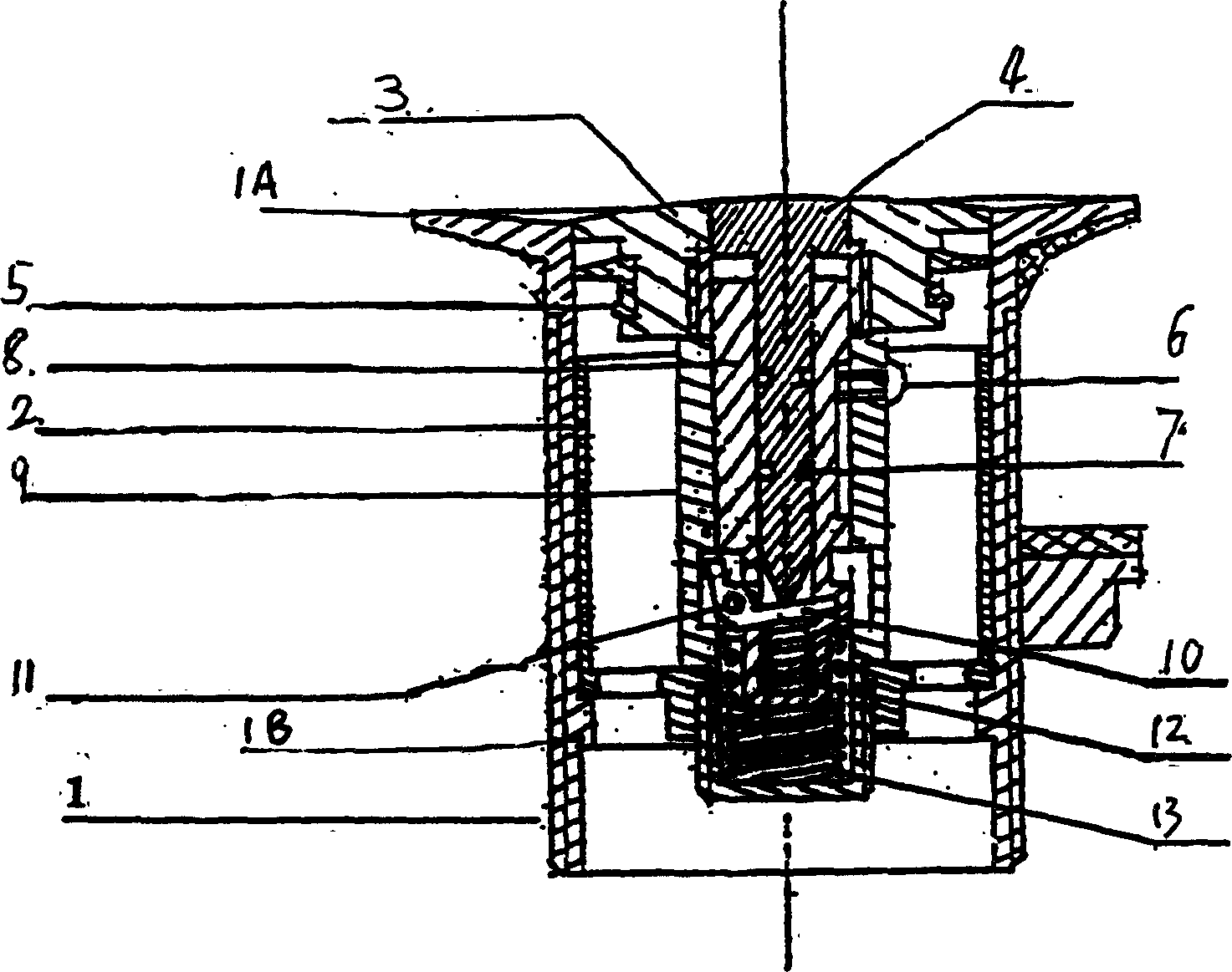
[0024] see figure 1 , the drainer of the present invention includes: a drain head 1 with a flange 1A on the top, a pressure lifting mechanism put into the drain head 1, a hydrophobic sleeve 2 inserted in the lower part, and screwed to each other, the drain sleeve 2 The lower end is supported by a cast stopper 1B in the lower end of the drain head 1 .

[0025] see Figure 1-8 , the touch pressure lifting mechanism includes: lifting cover 3, mandrel 4, sealing water pad 5, positioning screw 6, O-shaped sealing ring 7, lifting shaft 8, lifting body 9, active wedge 10, wedge fixing Pin 11, wedge top spring 12 and main top spring 13.

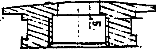
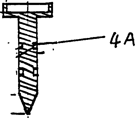
[0026] The mandrel 4 is inserted into the groove of the lifting cover 3, the top of the cover 3 matches the inner hole of the drain head 1, and the diameter below it is smaller, and a water sealing pad 5 is matched between the top and the bottom. The central part of the mandrel 4 is processed with at least one circular groove 4A, and an O-ring 7 i...


PUM


Abstract

A down device includes a drain head with a flange at the top, a contact lifting unit on the head with a dewatering jacket sleeved at the bottom connected by screw, the bottom of the dewater jacket is supported yb a casting block in the drainage head bottom. Said contact lifting unit includes: a lifting enclosing cover, a core axle, a water enclosing cushion, positioning screws, O-type seal loop, a lift shaft, a lifter, detachable wedge blocks, the block fixing bolts, and detachable block top sprigs and a main top spring.

Description

technical field [0001] The invention relates to a sanitary ware drainer, in particular to a drainer arranged in washbasins, bathtubs, washing tanks and the like. Background technique [0002] As we all know, sanitary ware, such as basins, bathtubs, etc., all have drains, and drains are arranged in the drains, and the performance of the drains will directly affect the use of the sanitary ware. The inventor has previously designed a sanitary ware drainer (ZL01254544.9) with an elastic lifting mechanism. In this mechanism, a pull hook moves in the groove. Since the pull hook is made of rigid material, the contact surface in the groove is small. It is easy to flatten the curved surface in the groove and cause the lifting mechanism to fail; and there is also the defect that dirt such as hair is not easy to clean. Contents of the invention [0003] The technical problem to be solved in the present invention is to design a touch-pressure lifting and falling device to overcome th...

Claims


Application Information

Patent Timeline
Patent Type & Authority Patents(China)
IPC IPC(8): E03C1/22A47K1/14
Inventor 李荣春
Owner 李荣春
Why Eureka
Try Eureka