Key structure

A key and limit structure technology, applied in key modules, electrical components, electrical switches, etc., can solve the problems of increased proportion, unstable feedback force of pressing the keycap, unstable pressing stroke, etc.

Active Publication Date: 2019-11-12
DARFON ELECTRONICS (SUZHOU) CO LTD +1
View PDF14 Cites 0 Cited by
  • Summary
  • Abstract
  • Description
  • Claims
  • Application Information

AI Technical Summary

Problems solved by technology

The keycap and the scissors bracket are usually connected by a connecting structure, but in order to make the scissors bracket move smoothly (for example, the bracket rotates relative to the bottom plate and the keycap) and to facilitate assembly, the strength of the connection structure is usually not strong, and will with gap
However, an excessively large gap will easily cause the keycap to vibrate when the key structure is actuated, which will affect the user's feel when pressing the keycap.
In addition, the aforementioned clearance will also affect the stability of the height of the key structure (or the highest position of the key cap). For example, the key cap may shake relative to the scissor foot bracket, so that the vertical position of the key cap will change when it is not pressed.
When the size of the key structure is small, the above-mentioned looseness causes the vertical position change of the key cap to increase in proportion to the overall height of the key structure (or the stroke of the key cap moving up and down), which makes the user feel bad when operating the key structure, such as pressing The feedback force of the keycap is unstable, the pressing stroke is unstable, etc.

Method used


Image

  • Key structure
  • Key structure
  • Key structure

Examples


Embodiment Construction

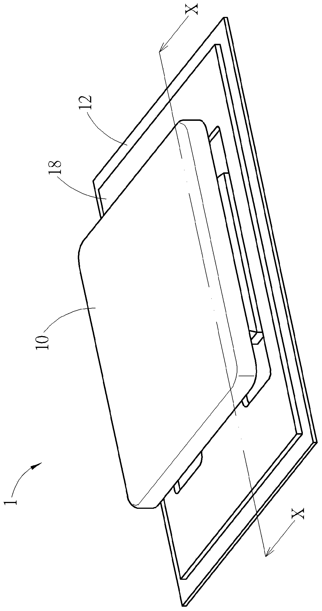
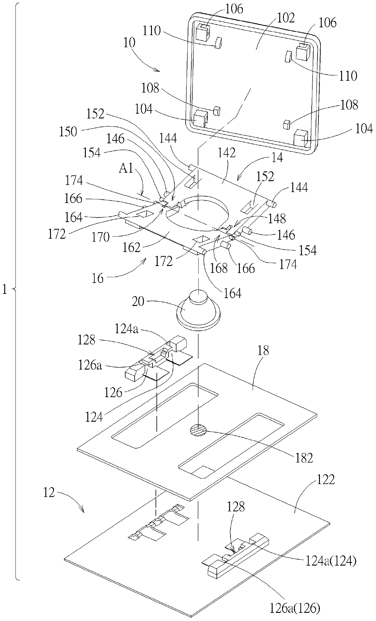
[0047] see figure 1 and figure 2 . The key structure 1 according to an embodiment includes a keycap 10 , a base 12 , a first bracket 14 , a second bracket 16 , a switch circuit board 18 and an elastic reset member 20 . The base 12 is arranged below the keycap 10, and the first bracket 14 and the second bracket 16 are relative to the rotation axis A1 (shown by a dotted line on figure 2 Middle) are pivotally connected to each other and are respectively connected between the keycap 10 and the base 12, the switch circuit board 18 is placed on the base 12, and the elastic return member 20 corresponds to the switch 182 of the switch circuit board 18 (shown in a circle with a hatched line). figure 2 Middle) placed on the switch circuit board 18. The keycap 10 can move vertically up and down relative to the base 12 through the first support 14 and the second support 16 , and the keycap 10 moving downward can press the elastic reset member 20 to trigger the switch 182 . In actua...


PUM


Abstract

The invention discloses a key structure, which comprises a key cap, a base and two brackets pivotally connected relative to a rotation axis and connected between the key cap and the base, wherein thekey cap can move vertically relative to the base via the two brackets. The key structure uses additional structural interaction to increase the actuating stability of a component. For example, the keycap and the two brackets can be provided with limiting structures, the sum of the structural interference gaps is maintained within a predetermined range, and thus, the two brackets can actuate smoothly relatively and excessive wear can be avoided. As another example, one of the brackets can be provided with an abutment structure that selectively interferes with the base to limit the highest position of the key cap. The structural configuration of the invention is advantageous for the actuation of the key structure to be stable.

Description

technical field [0001] The invention relates to a mechanical key structure, in particular to a mechanical key structure in which a key cap is supported and actuated by two brackets. Background technique [0002] The mechanical key structure has a plurality of components that are connected to each other and act relative to each other. In order to make each component move smoothly, a considerable gap is left between each component in principle to avoid structural interference or excessive friction during actuation. In the traditional key structure with scissor legs, the keycap can move up and down relative to the base plate through the scissor legs. The keycap and the scissors bracket are usually connected by a connecting structure, but in order to make the scissors bracket move smoothly (for example, the bracket rotates relative to the bottom plate and the keycap) and to facilitate assembly, the strength of the connection structure is usually not strong, and will with gaps. ...

Claims


Application Information

Patent Timeline
Patent Type & Authority Applications(China)
IPC IPC(8): H01H13/705
CPCH01H13/705H01H2233/074
Inventor 赵令溪
Owner DARFON ELECTRONICS (SUZHOU) CO LTD
Why Eureka
Try Eureka