An on-orbit calibration method of microwave radiometer based on real-time monitoring of antenna pattern

A microwave radiometer and antenna pattern technology, which is applied to antenna radiation patterns, measuring devices, measuring electrical variables, etc., can solve the problems of narrowing the antenna beam width and the inability to accurately calibrate the antenna deformation.

Active Publication Date: 2021-04-02
NAT SATELLITE METEOROLOGICAL CENT
View PDF8 Cites 0 Cited by
  • Summary
  • Abstract
  • Description
  • Claims
  • Application Information

AI Technical Summary

Problems solved by technology

[0002] In the microwave and millimeter wave bands, in order to improve the sufficient spatial resolution of the satellite-mounted microwave radiometer to observe the earth, it has to use a large-aperture antenna to reduce the beam width of the antenna. The antenna aperture often reaches several meters or even tens of meters, and the satellite itself is difficult to carry. A blackbody of sufficient size to calibrate the whole radiometer can only rely on a small blackbody to calibrate the receiver at the rear end of the antenna at two points, and the deformation of the exposed main reflector and secondary reflector of the antenna cannot be accurately calibrated

Method used


Image

  • An on-orbit calibration method of microwave radiometer based on real-time monitoring of antenna pattern

Examples


Embodiment 1

[0039] This embodiment illustrates the specific implementation of an on-orbit calibration method for a microwave radiometer based on real-time monitoring of antenna pattern according to the present invention.

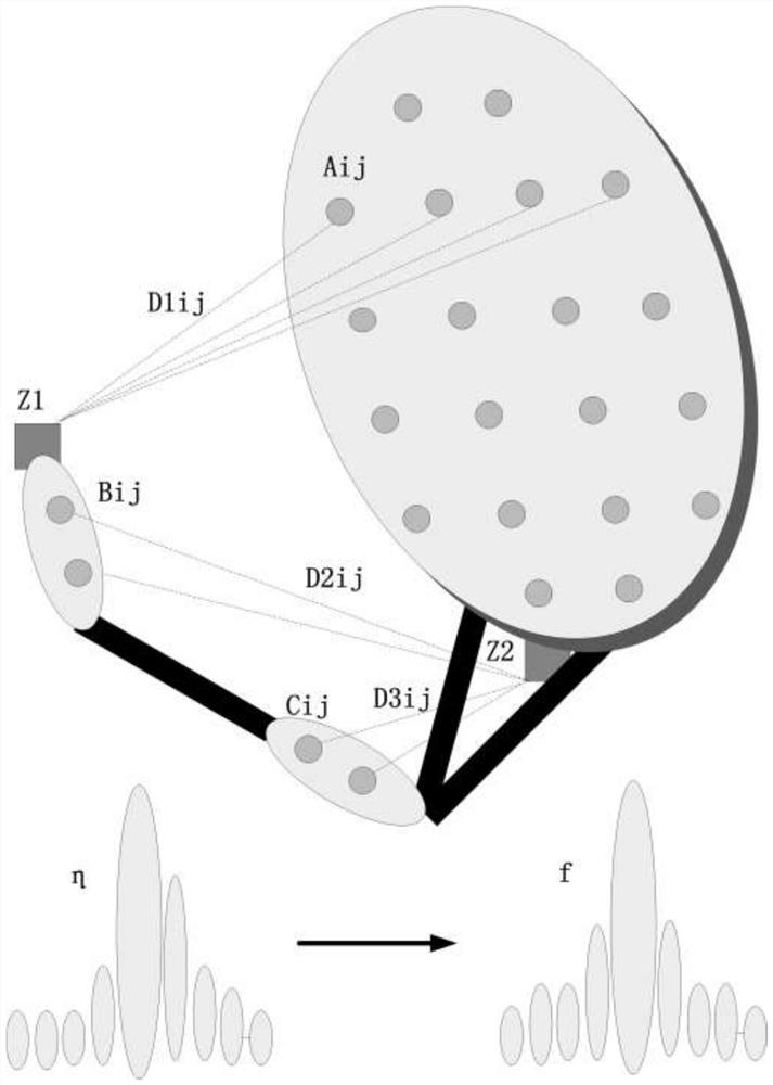
[0040] Step 1. During specific implementation, install laser distance measuring devices Z1 and Z2, specifically including the following sub-steps:

[0041] Step 1.1 Apply multiple laser reflective materials on the main reflective surface of the antenna;

[0042] Among them, the laser ranging devices Z1 and Z2 emit laser light to irradiate the application material, Z1 and Z2 receive the laser signal reflected by the application material, Z1 and Z2 calculate the distance between the application material and the surface of the antenna, and set it to Grid shape, the grid spacing is 1 / 10 of the antenna diameter, and the grid covers the entire antenna main reflecting surface;

[0043] Among them, the laser reflective material in row i and column j is denoted as Aij;

[0044...


PUM


Abstract

The invention relates to a microwave radiometer in-orbit calibration method based on antenna directional diagram real-time monitoring, and belongs to the technical field of the microwave radiometer calibration. The in-orbit calibration method comprises the following steps: step one, mounting laser ranging devices Z1 and Z2, and recording the distance between a laser reflecting material and each laser ranging device under various moments; step two, monitoring geometric equation of each laser ranging device, and recording the distance variation observed at the previous moment and the later moment in real time; step three, computing a new antenna directional diagram f to obtain atmospheric brightness temperature observation output II; and step four, repeating the real-time monitoring on the antenna directional diagram, and performing real-time calibration to obtain real atmospheric brightness temperature information. Through the method disclosed by the invention, the large-aperture antenna microwave radiometer calibration difficult can be solved, and the precision is high.

Description

technical field [0001] The invention relates to an on-orbit calibration method of a microwave radiometer based on real-time monitoring of an antenna pattern, and belongs to the technical field of microwave radiometer calibration. Background technique [0002] In the microwave and millimeter wave bands, in order to improve the sufficient spatial resolution of the satellite-mounted microwave radiometer to observe the earth, it has to use a large-aperture antenna to reduce the beam width of the antenna. The antenna aperture often reaches several meters or even tens of meters, and the satellite itself is difficult to carry. A blackbody of sufficient size to calibrate the whole radiometer can only rely on a small blackbody to calibrate the receiver at the rear end of the antenna at two points, and the deformation of the exposed main reflector and secondary reflector of the antenna cannot be accurately calibrated . Contents of the invention [0003] The purpose of the present i...

Claims


Application Information

Patent Timeline
Patent Type & Authority Patents(China)
IPC IPC(8): G01R35/00G01R29/10
CPCG01R29/10G01R35/005
Inventor 安大伟张志清
Owner NAT SATELLITE METEOROLOGICAL CENT
Why Eureka
Try Eureka