Multifunctional rope releasing equipment with rescue function

A multi-functional and equipment technology, applied in life-saving equipment, fire rescue, building rescue, etc., can solve problems such as accidental injury to personnel glass, casualty accidents of descending devices, and great impact

Inactive Publication Date: 2019-11-22
吴超然
View PDF0 Cites 0 Cited by
  • Summary
  • Abstract
  • Description
  • Claims
  • Application Information

AI Technical Summary

Problems solved by technology

[0022] After studying the use process of the above-mentioned existing descending device and the user's feelings, it is found that the existing descending device with the descending rope has many shortcomings: this descending device is provided on the floor of the fire place to provide This floor is used by escape personnel, because this floor is the ignition point of fire, which is a threat to the descending device suspended on this floor, and the existing descending device needs to be inspected regularly. Generally, individual buyers lack this awareness due to troubles, which also poses a threat to The normal use of the descending device has caused potential hidden dangers, and there have been casualty accidents using the descending device; the descending height of the existing descending devices with descending ropes is controlled below 100 meters. The vol...

Method used


Image

  • Multifunctional rope releasing equipment with rescue function
  • Multifunctional rope releasing equipment with rescue function
  • Multifunctional rope releasing equipment with rescue function

Examples


Embodiment Construction

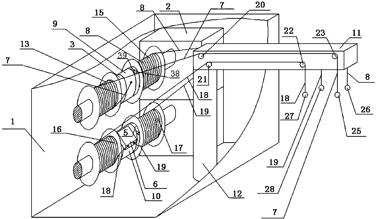
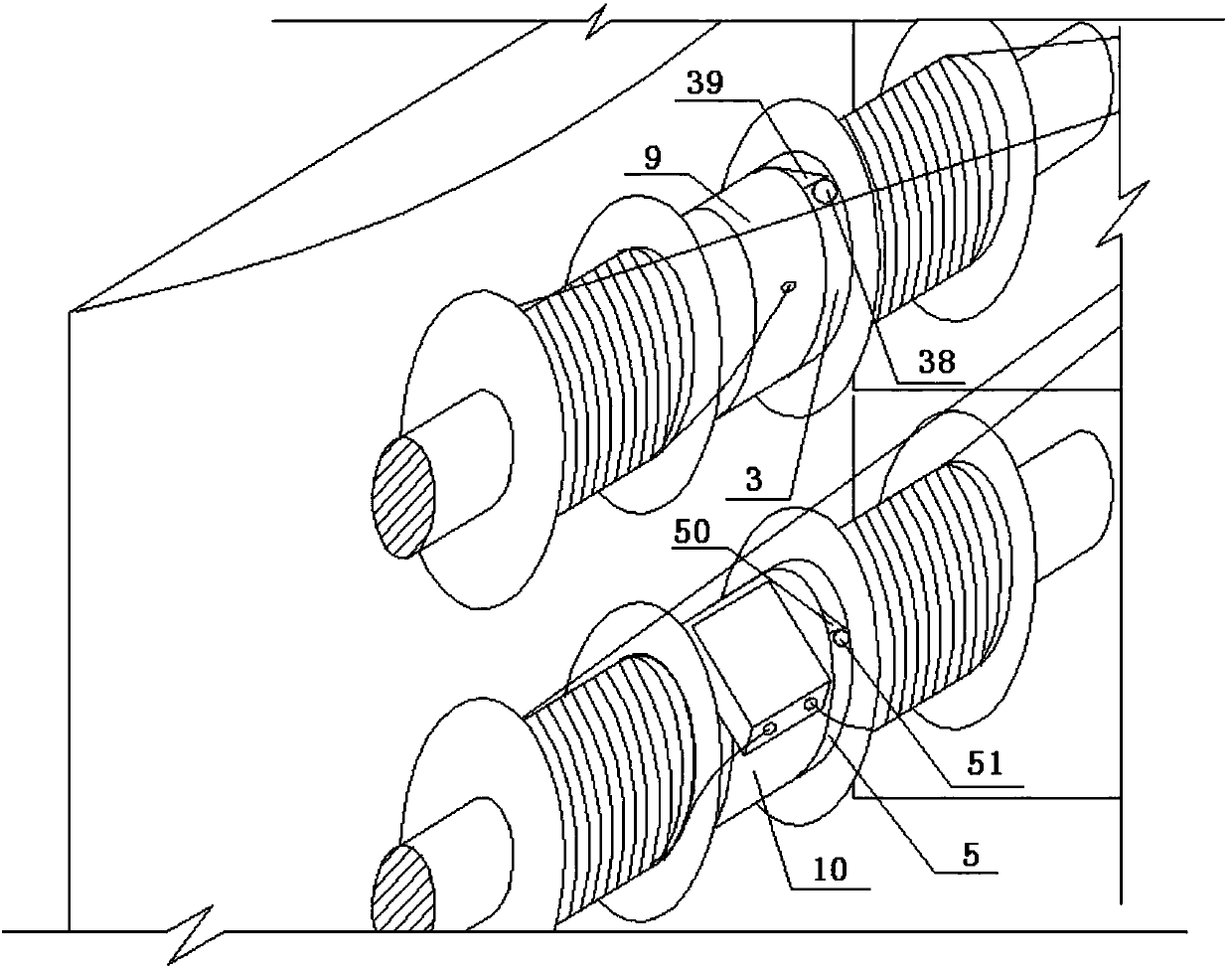
[0101] Such as figure 1 as shown, figure 1 It is a schematic diagram of the oblique view of the first embodiment of the present application. The multifunctional rope releasing device includes a housing 1, an electric motor 2, a reel 3, a reel 5, a descender 6, a pull rope 7, a pull rope 8, a ring 9, a ring 10, a cantilever 11, and a column 12 , the above-mentioned electric motor 2, reel 3, reel 5, slow descender 6, stay rope 7, stay rope 8, ring 9, ring 10, column 12 are arranged in the housing, electric motor 2 and reel 3, The connection of the reel 5 can drive the reel 3 and the reel 5 to rotate. The above-mentioned ring 9 is set on the outer periphery of the reel 3 and can rotate around the reel 3. The above-mentioned ring 10 is set on the outer periphery of the reel 5 and can surround the reel 5 rotation, the above-mentioned descending device 6 is arranged on the ring 10, and one end of the above-mentioned stay rope 7 and stay rope 8 is fixedly connected on the ring 9. ...


PUM


Abstract

The invention provides multifunctional rope releasing equipment with a rescue function. The multifunctional rope releasing equipment comprises a power transmission system or a hydraulic transmission system or a pneumatic transmission system, winding drums or rotating shafts, and a descent control device, wherein rotary shafts of a motor of the power transmission system or the hydraulic transmission system or the pneumatic transmission system can drive the winding drums or the rotating shafts to rotate; circular rings are arranged on the winding drums or the rotating shafts in a sleeving mode,and the circular rings can rotate around the winding drums or the rotating shafts; blocking surfaces are arranged on the circular rings, and blocking pieces are arranged on the winding drums or the rotating shafts; the descent control device is arranged on the corresponding circular ring, and descent control ropes of the descent control device extend out of the descent control device and are woundaround the winding drums or the rotating shafts; and a cable connected with the motor is connected with a power supply through a main contact of a contactor, a coil of the contactor is connected witha PLC and the power supply to form a loop, and a button or a touch screen connected with the PLC can control the main contact of the contactor to be closed and enable the motor to rotate forward or reversely.

Description

technical field [0001] This application belongs to an escape device. Background technique [0002] Fires in high-rise buildings have always attracted people's attention, and the reliability of fire elevators in the event of a fire is worth pondering. There is also the arm-raising fire truck used in the existing fire-fighting and lifesaving, which can generally implement fire fighting and rescue at a height of 53 meters, and the climbing of the fire-fighting ladder truck has a limit. Usually, the fire-fighting ladder truck can only rise to 80 of the limit value. % or so, if the wind force on the ground reaches level 4 to 5, the fire-fighting aerial ladder truck will not be able to raise the operation. In this way, once a high-rise building above 50 meters catches fire or people are trapped, it will be difficult for the fire-fighting aerial ladder to play a role. Rely on one's own ability to escape, but some high-rise buildings have incomplete fire protection facilities, fire...

Claims


Application Information

Patent Timeline
IPC IPC(8): A62B1/10A62B1/12A62B1/18A62C31/00
CPCA62B1/10A62B1/12A62B1/18A62C31/00
Inventor 吴超然
Owner 吴超然
Why Eureka
Try Eureka