Check patentability & draft patents in minutes with Patsnap Eureka AI!

A kind of extension heat dissipation power distribution cabinet

A power distribution cabinet and heat dissipation technology, applied in the field of extended heat dissipation power distribution cabinet, can solve the problems of inability to prevent non-workers from touching, unable to effectively shelter from rain, and reduce heat dissipation performance, so as to increase ventilation performance and improve heat exchange. , the effect of increasing the heat dissipation performance

Active Publication Date: 2020-12-11
宿迁凯运电力科技有限公司
View PDF6 Cites 0 Cited by
  • Summary
  • Abstract
  • Description
  • Claims
  • Application Information

AI Technical Summary

Problems solved by technology

[0002] The power distribution cabinet in traditional technology usually adopts a fixed structure, which can only play the role of protection and barrier. The heat dissipation surface is limited to the area of ​​the shell, and when it is under high load, the barrier of the cabinet will undoubtedly greatly reduce the heat dissipation performance, which cannot be compared with Rapid heat exchange with the outside world; however, the exposed power distribution cabinet structure is unsafe, unable to prevent non-staff from touching it, and cannot effectively avoid rain. A cabinet with high heat dissipation efficiency can change the above situation

Method used


Image

  • A kind of extension heat dissipation power distribution cabinet
  • A kind of extension heat dissipation power distribution cabinet
  • A kind of extension heat dissipation power distribution cabinet

Examples


Embodiment Construction

[0027] The following will clearly and completely describe the technical solutions in the embodiments of the present invention with reference to the accompanying drawings in the embodiments of the present invention. Obviously, the described embodiments are only some, not all, embodiments of the present invention.

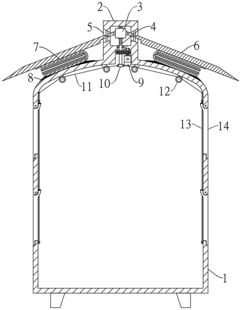
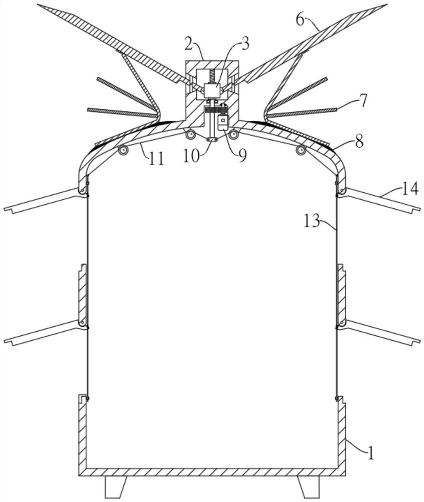
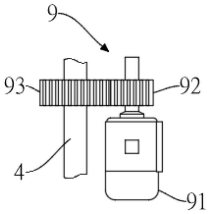
[0028] refer to Figure 1-6 , an extended heat dissipation power distribution cabinet, including a cabinet body 1, an extension frame 2 is fixedly connected to the top of the cabinet body 1, a cavity is opened in the extension frame 2, baffles 6 are symmetrically arranged on both sides of the extension frame 2, and the baffles The plate 6 is rotatably connected to the extension frame 2 and extends into the cavity. An extended heat conducting member 7 is installed between the baffle plate 6 and the cabinet body 1, and a lifting mechanism is arranged in the cavity.

[0029] The gap between the bottom end of the stretchable heat conduction member 7 and the outer surface...


PUM


Abstract

The invention discloses an extended heat dissipation type power distribution cabinet. The power distribution cabinet comprises a cabinet body. An extension frame is fixedly connected to a top end of the cabinet body, a cavity is arranged in the extension frame. Baffle plates are symmetrically arranged on two sides of the extension frame, the baffle plates are rotationally connected to the extension frame and are extended into the cavity, an extension type heat conduction piece is installed between each baffle plate and the cabinet body, and a lifting mechanism is arranged in the cavity. The power distribution cabinet adopts an extension type heat dissipation design. Compared with a traditional technology, by using the power distribution cabinet of the invention, a heat dissipation area ofa top surface is increased so that heat exchange with the outside world is better performed, and ventilation performance of a side surface is improved. When hot air in the cabinet body is taken away by a top surface, the outside air quickly enters into the cabinet body under an effect of atmospheric pressure so as to realize circulation of an air path. The power distribution cabinet adopts a top surface and side surface linkage type design, the heat dissipation area is large when the power distribution cabinet is unfolded, an extra space is not required to be used temporarily after the power distribution cabinet is stored, rain can be sheltered, and a non-staff can be prevented from touching the internal poriton of the power distribution cabinet.

Description

technical field [0001] The invention relates to the technical field of power distribution cabinets, in particular to an extended heat dissipation power distribution cabinet. Background technique [0002] The power distribution cabinet in traditional technology usually adopts a fixed structure, which can only play the role of protection and barrier. The heat dissipation surface is limited to the area of ​​the shell, and when it is under high load, the barrier of the cabinet will undoubtedly greatly reduce the heat dissipation performance, which cannot be compared with Rapid heat exchange with the outside world; however, the exposed power distribution cabinet structure is unsafe, unable to prevent touch by non-staff, and unable to effectively avoid rain. A cabinet with high heat dissipation efficiency can change the above situation. Contents of the invention [0003] The object of the present invention is to solve the above problems, and propose an extended heat dissipation...

Claims


Application Information

Patent Timeline
Patent Type & Authority Patents(China)
IPC IPC(8): H02B1/30H02B1/56
CPCH02B1/30H02B1/565
Inventor 徐鑫
Owner 宿迁凯运电力科技有限公司
Features
  • R&D
  • Intellectual Property
  • Life Sciences
  • Materials
  • Tech Scout
  • Unparalleled Data Quality
  • Higher Quality Content
  • 60% Fewer Hallucinations
Learn More