Method, terminal device and network side device for multi-beam transmission uplink channel

A terminal equipment, multi-beam technology, applied in the field of communications, can solve the problem of inability to transmit uplink channels in multiple beams, and achieve the effect of improving uplink transmission efficiency

Active Publication Date: 2022-03-18
VIVO MOBILE COMM CO LTD
View PDF3 Cites 0 Cited by
  • Summary
  • Abstract
  • Description
  • Claims
  • Application Information

AI Technical Summary

Problems solved by technology

[0004] The purpose of the embodiments of the present invention is to provide a method for transmitting uplink channels with multiple beams, terminal equipment and network side equipment, so as to solve the problem that the prior art cannot transmit uplink channels based on multiple beams

Method used


Image

  • Method, terminal device and network side device for multi-beam transmission uplink channel
  • Method, terminal device and network side device for multi-beam transmission uplink channel
  • Method, terminal device and network side device for multi-beam transmission uplink channel

Examples


Embodiment Construction

[0026] The following will clearly and completely describe the technical solutions in the embodiments of the present invention with reference to the accompanying drawings in the embodiments of the present invention. Obviously, the described embodiments are some of the embodiments of the present invention, but not all of them. Based on the embodiments of the present invention, all other embodiments obtained by persons of ordinary skill in the art without creative efforts fall within the protection scope of the present invention.

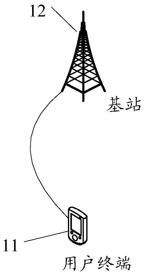
[0027] see figure 1 , figure 1 A schematic diagram of a network architecture provided by an embodiment of the present invention. Such as figure 1 As shown, it includes a user terminal 11 and a base station 12, wherein the user terminal 11 can be a terminal equipment (UE, User Equipment), for example: it can be a mobile phone, a tablet computer (Tablet Personal Computer), a laptop computer (Laptop Computer), Terminal-side devices such as personal dig...


PUM


Abstract

The embodiment of the present invention discloses a method for transmitting an uplink channel with multiple beams, a terminal device and a network side device. The method includes: receiving configuration information, wherein the configuration information includes multiple Uplink beam information; the plurality of uplink beam information has an association relationship with related parameters of the uplink channel. Embodiments of the present invention enable the terminal device to use multiple uplink beam information to transmit uplink channels according to the correlation between the multiple uplink beam information and the related parameters of the uplink channel, thereby effectively improving the uplink transmission efficiency of the communication system.

Description

technical field [0001] The present invention relates to the communication field, in particular to a method for multi-beam transmission uplink channel, terminal equipment and network side equipment. Background technique [0002] The fifth-generation (5G) mobile communication system new air interface (NR, New Radio) introduces large-scale antenna technology, which can better support multi-user-multiple-input multiple-output (MU-MIMO, Multi-User Multiple-Input Multiple-Output ) antenna technology. In order to reduce the equipment cost and baseband processing complexity caused by large-scale antenna arrays, the digital-analog hybrid beamforming technology is used to achieve a rough match between the transmitted signal and the channel. [0003] However, in the digital-analog hybrid beamforming technology, there is still a lack of schemes for transmitting uplink channels based on multi-beams, resulting in low uplink transmission efficiency of the communication system. Contents ...

Claims


Application Information

Patent Timeline
Patent Type & Authority Patents(China)
IPC IPC(8): H04W72/04H04B7/0408H04B7/06H04B7/08
CPCH04W72/046H04B7/0408H04B7/0617H04B7/086H04W72/23H04B7/0695H04B7/0404H04W76/27H04L25/0226H04W72/53
Inventor 杨宇孙鹏孙晓东
Owner VIVO MOBILE COMM CO LTD
Why Eureka
Try Eureka