Long-distance resonance light wireless energy supply device based on telescope optical modulator

An optical modulator and wireless energy supply technology, applied in optics, circuit devices, optical components, etc., can solve the problems of limited transmission power and transmission distance of the resonant light energy supply system, and the expansion of influence, so as to reduce diffraction loss and stabilize The effect of power output

Inactive Publication Date: 2020-04-10
TONGJI UNIV
View PDF4 Cites 2 Cited by
  • Summary
  • Abstract
  • Description
  • Claims
  • Application Information

AI Technical Summary

Problems solved by technology

However, due to the limitation of diffraction loss, the original resonant optical power supply system has limited transmission power and transmission distance, and cannot provide stable high-power power supply for remote IoT devices (such as drones), which affects its application in the Internet of Things. Expansion of the energy supply field

Method used


Image

  • Long-distance resonance light wireless energy supply device based on telescope optical modulator
  • Long-distance resonance light wireless energy supply device based on telescope optical modulator
  • Long-distance resonance light wireless energy supply device based on telescope optical modulator

Examples


Embodiment 1

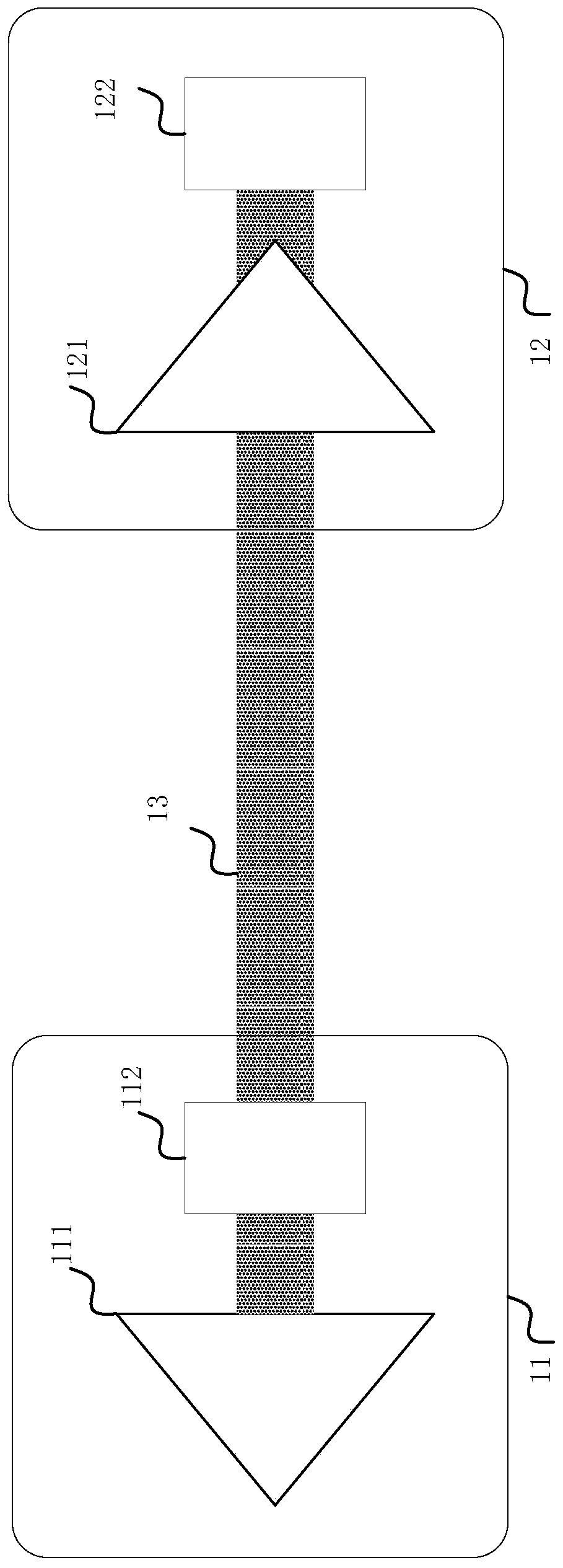
[0039] Such as Figure 4 As shown, the transmitter 41 in this embodiment includes the following parts:

[0040] a first retro-reflector 411;

[0041] b the gain module 412 on the right side of the first retro-reflector 411;

[0042] c The telescope optical modulator on the right side of the gain block 412 .

[0043] Figure 4 The receiver 42 of the illustrated embodiment includes the following:

[0044] a second retro-reflector 421;

[0045] b photoelectric conversion module 422 .

[0046] exist Figure 4 Among them, the transmitter 41 and the receiver 42 constitute a resonant optical wireless energy supply device. Wherein, the resonant light beam is generated in the resonant cavity formed by the first retro-reflector 411 and the second retro-reflector 422 . Due to the existence of the retro-reflector, when the relative positions of the receiver 41 and the transmitter 42 change, the system can ensure that the resonant light beam can always pass through the gain module ...

Embodiment 2

[0048] Such as Figure 5 As shown, a through-type structure is designed in this example. Wherein, the transmitter 51 includes the following parts:

[0049] a cat's-eye type first retro-reflector composed of a rear reflector 511 with high reflectivity and a light modulation lens 512;

[0050] b the gain block 513 on the right side of the first retro-reflector;

[0051] c is on the right side of the gain module 513, the telescopic optical modulator 514 with spot compression capability.

[0052] Figure 5 The receiver 52 of the illustrated embodiment includes the following:

[0053] a cat's-eye type second retro-reflector formed by a rear reflector 522 with partial transmittance and a light modulation lens 521;

[0054] b photoelectric conversion module 523 .

[0055] exist Figure 5 In , the first retro-reflector and the second retro-reflector constitute a free-space stimulated emission resonant cavity. Due to the frequency selection and amplification functions of the ga...

Embodiment 3

[0058] Such as Figure 6 As shown, this example presents a folded structure, which is more compact than a linear structure, which is beneficial to device integration and packaging. The transmitter 61 in this embodiment includes the following parts:

[0059] a cat's-eye type first retro-reflector made of rear high reflection mirror 613 and light modulation lens 614;

[0060] b the gain block 611 and the beam folding mirror 615 on the left side of the first retro-reflector;

[0061] c is the telescope optical modulation module 612 on the left side of the gain module.

[0062] Figure 6 The receiver 62 of the illustrated embodiment includes the following:

[0063] a cat's-eye type second retro-reflector made of rear partial reflector 621 and light adjustment lens 622;

[0064] b photoelectric conversion module 623.

[0065] exist Figure 6 In , through the reflection of the beam folding mirror 615, the resonant light entering the gain module is reflected and propagates upw...


PUM


Abstract

The invention relates to a long-distance resonance light wireless energy supply device based on a telescope optical modulator. The device comprises a transmitter and a receiver, a first retro-reflector and a gain module are arranged in the transmitter. A second retro-reflector and a photoelectric conversion module are sequentially arranged in the receiver; a resonant light resonant cavity is formed between the first retro-reflector and the second retro-reflector; a telescope optical modulator is arranged in the transmitter; and the first retro-reflector, the gain module and the telescope optical modulator are sequentially arranged along an optical path. Compared with the prior art, the long-distance resonance light wireless energy supply device has the advantages that resonance light is compressed and stabilized, diffraction loss is reduced, high-power long-distance stable energy output is achieved, and the like.

Description

technical field [0001] The invention relates to the field of long-distance wireless optical charging, in particular to a long-distance resonant light wireless energy supply device based on a telescope optical modulator. Background technique [0002] IoT technology digitizes the world by connecting everything, making our life more intelligent and comfortable. With the popularization of IoT technology, its application in various fields has become increasingly complex. The demand for data communication and the amount of information processing of IoT devices have increased sharply, and energy consumption has also increased. However, the traditional cable power supply method is very inconvenient and not suitable for mobile IoT devices; battery power supply is suitable for mobile device power supply, but it is limited by battery capacity, volume, and weight. How to effectively supply energy for IoT devices has become one of the challenges for the continuous development of IoT tec...

Claims


Application Information

Patent Timeline
Patent Type & Authority Applications(China)
IPC IPC(8): H02J50/30G02B17/08
CPCG02B17/08H02J50/30
Inventor 白云峰刘庆文熊明亮邓浩张清清
Owner TONGJI UNIV
Why Eureka
Try Eureka