
Lock and speed reducer thereof
A technology of reduction device and reduction ratio, applied in the field of locks, can solve problems such as hidden dangers of property safety, false locks, and current rise, and achieve the effects of reasonable structure, prevention of false locks, flexible and reliable control
- Summary
- Abstract
- Description
- Claims
- Application Information
AI Technical Summary
Problems solved by technology
Method used
Image

Examples
Embodiment 1
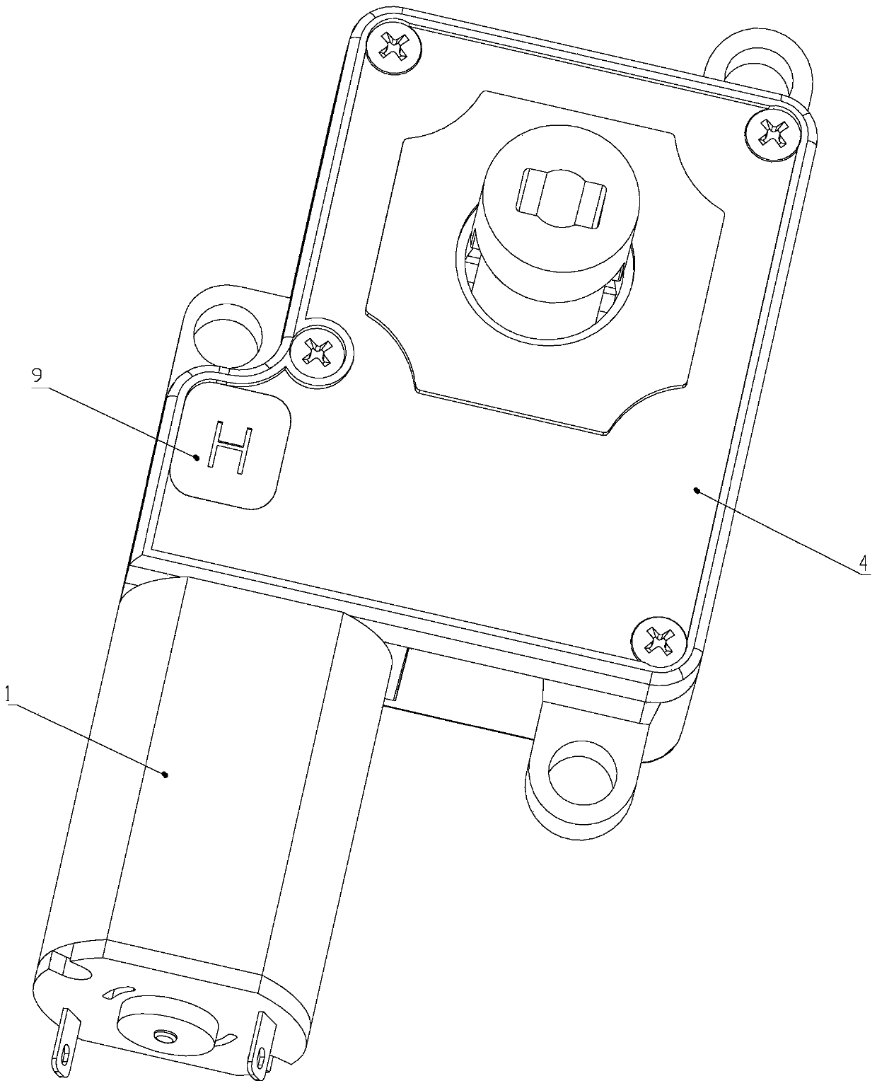
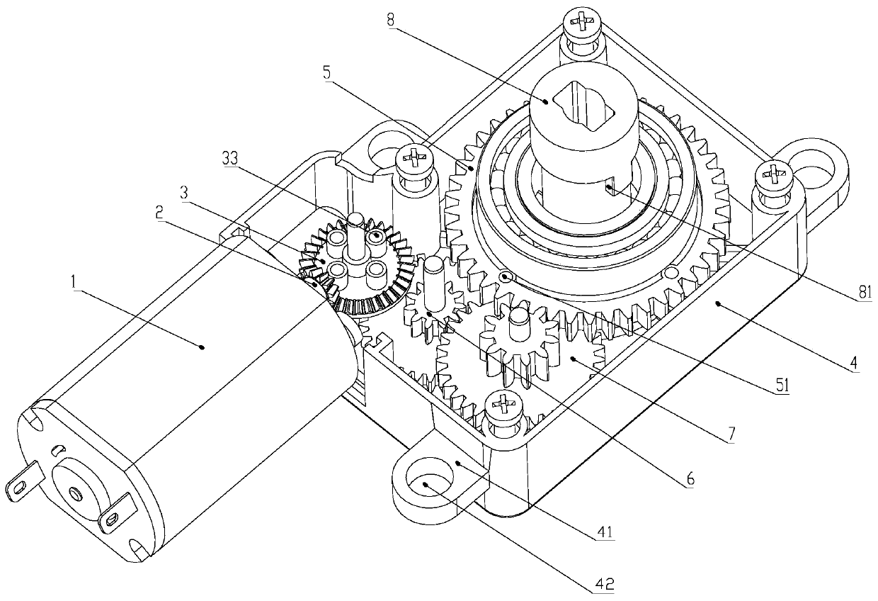
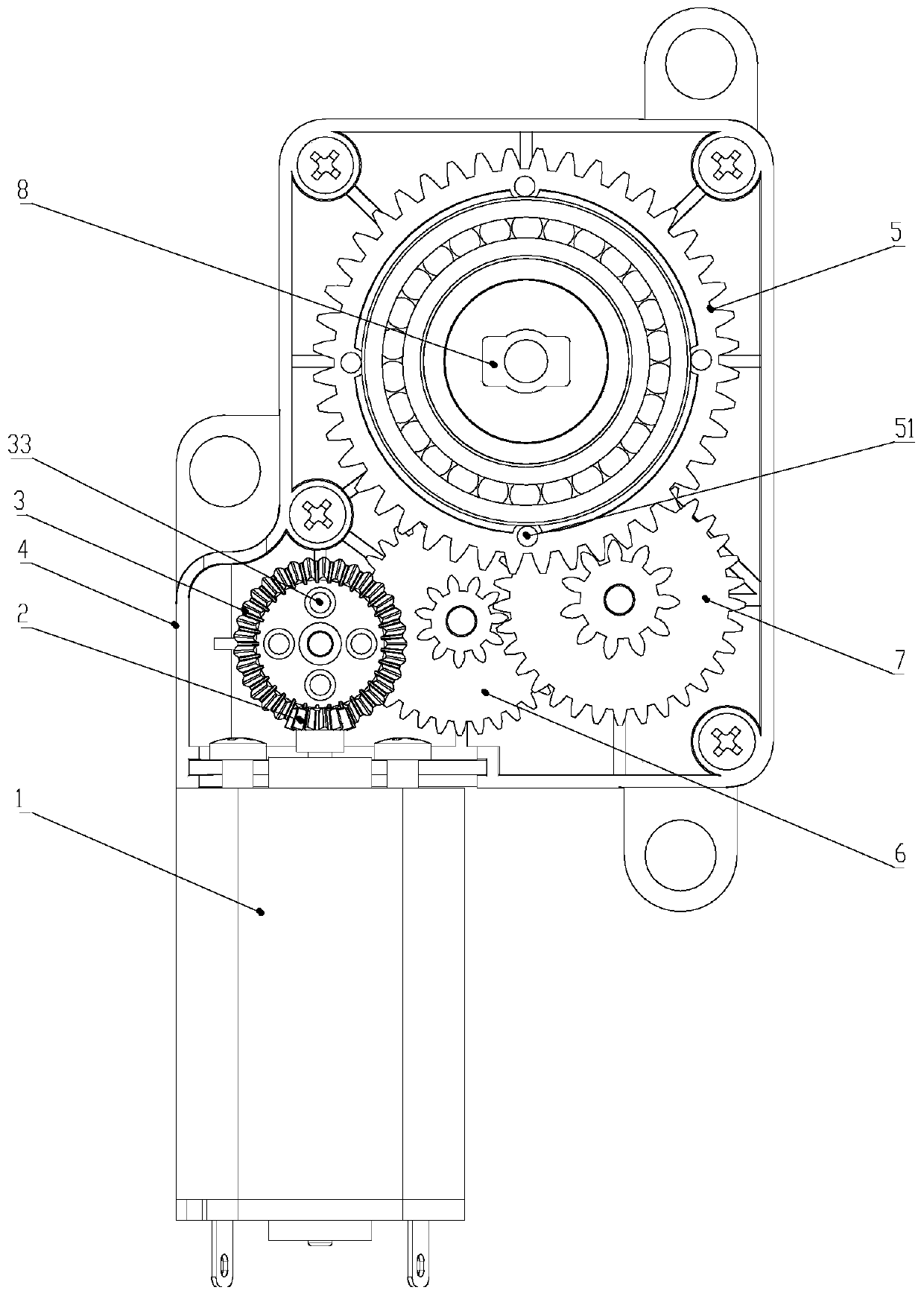
[0028] A lock includes a deceleration device. A speed reduction device, as shown in the figure, includes a housing 4, a motor 1 and a bevel gear 2, the housing 4 is connected to the motor 1, the housing 4 is provided with lugs 41, and the lugs 41 are provided with screw holes 42 , The motor 1 is provided with a bevel gear 2, and also includes a first gear part 3, a gear set, a drive gear 5 and a rotating shaft 8, the bevel gear 2 meshes with the first gear part 3, and the first gear part 3 meshes with the gear set , the gear set meshes with the driving gear 5 , the driving gear 5 is provided with a rotating shaft 8 , and the first gear member 3 is provided with five first magnetic parts 33 .
[0029] The driving gear 5 is provided with a second magnetic part 51, the first magnetic part 33 is a reed switch, and the second magnetic part 51 is a reed switch.
[0030] The housing 4 is provided with a circuit board 9 for sensing electric pulse signals of the first magnetic part 33...
Embodiment 2
[0040] A speed reduction device, as shown in the figure, includes a housing 4, a motor 1 and a bevel gear 2, the housing 4 is connected to the motor 1, the housing 4 is provided with lugs 41, and the lugs 41 are provided with screw holes 42 , The motor 1 is provided with a bevel gear 2, and also includes a first gear part 3, a gear set, a drive gear 5 and a rotating shaft 8, the bevel gear 2 meshes with the first gear part 3, and the first gear part 3 meshes with the gear set , the gear set meshes with the driving gear 5 , the driving gear 5 is provided with a rotating shaft 8 , and the first gear member 3 is provided with three first magnetic parts 33 .
[0041] The driving gear 5 is provided with a second magnetic part 51, the first magnetic part 33 is a Hall switch, and the second magnetic part 51 is a Hall switch.
[0042] The housing 4 is provided with a circuit board 9 for sensing electric pulse signals of the first magnetic part 33 and the second magnetic part 51 .
[...
Embodiment 3
[0052] A speed reduction device, as shown in the figure, includes a housing 4, a motor 1 and a bevel gear 2, the housing 4 is connected to the motor 1, the housing 4 is provided with lugs 41, and the lugs 41 are provided with screw holes 42 , The motor 1 is provided with a bevel gear 2, and also includes a first gear part 3, a gear set, a drive gear 5 and a rotating shaft 8, the bevel gear 2 meshes with the first gear part 3, and the first gear part 3 meshes with the gear set , the gear set meshes with the driving gear 5 , the driving gear 5 is provided with a rotating shaft 8 , and the first gear part 3 is provided with a first magnetic part 33 .
[0053] The driving gear 5 is provided with a second magnetic part 51, the first magnetic part 33 is a reed switch, and the second magnetic part 51 is a Hall switch.
[0054] The housing 4 is provided with a circuit board 9 for sensing electric pulse signals of the first magnetic part 33 and the second magnetic part 51 .
[0055] T...
PUM
 Abstract
Description
Claims
Application Information