Path planning method for multiple unmanned aerial vehicles to arrive at designated place simultaneously in three-dimensional environment

A path planning, multi-UAV technology, applied in three-dimensional position/channel control, vehicle position/route/altitude control, non-electric variable control, etc., can solve the problem of lack of simultaneous arrival application background, etc., to prevent premature and partial Convergence, high track quality, and the effect of reducing the search space

Active Publication Date: 2020-06-12
BEIJING INSTITUTE OF TECHNOLOGYGY
View PDF4 Cites 11 Cited by
  • Summary
  • Abstract
  • Description
  • Claims
  • Application Information

AI Technical Summary

Problems solved by technology

[0004] In the existing technology, the collaborative path planning of UAVs in the 3D environment mostly focuses on the generation of paths by geometric methods or the establishment of cooperative motion models, and lacks the application background of simultaneous arrival in the 3D environment: Sahingo et al. proposed a method based on genetic Algorithm (GA) multi-UAV flight path planning method, first calculates a feasible path with the gas method, and then uses the Bezier curve to smooth the path; Madhavan Shanmugavel et al. studied the collaborative Path planning problem, using dubin paths with clothoid arcs to generate paths for each UAV; Christoph Rasche et al. propose a multi-UAV path planning method in 3D environment, providing a solution for exploring disaster areas ; The present invention is mainly aimed at the specific application scenario where multiple unmanned people arrive at the target point at the same time, and combines UAV dynamic constraints, safety constraints, and terrain condition constraints to propose a new and practical multi-UAV collaborative path planning scheme

Method used


Image

  • Path planning method for multiple unmanned aerial vehicles to arrive at designated place simultaneously in three-dimensional environment
  • Path planning method for multiple unmanned aerial vehicles to arrive at designated place simultaneously in three-dimensional environment
  • Path planning method for multiple unmanned aerial vehicles to arrive at designated place simultaneously in three-dimensional environment

Examples


example

[0086] In order to verify the effectiveness of the path planning method for multiple unmanned aerial vehicles to arrive at the designated place at the same time in a three-dimensional environment, this embodiment uses the Matlab programming environment, and the relevant parameters are set as follows:

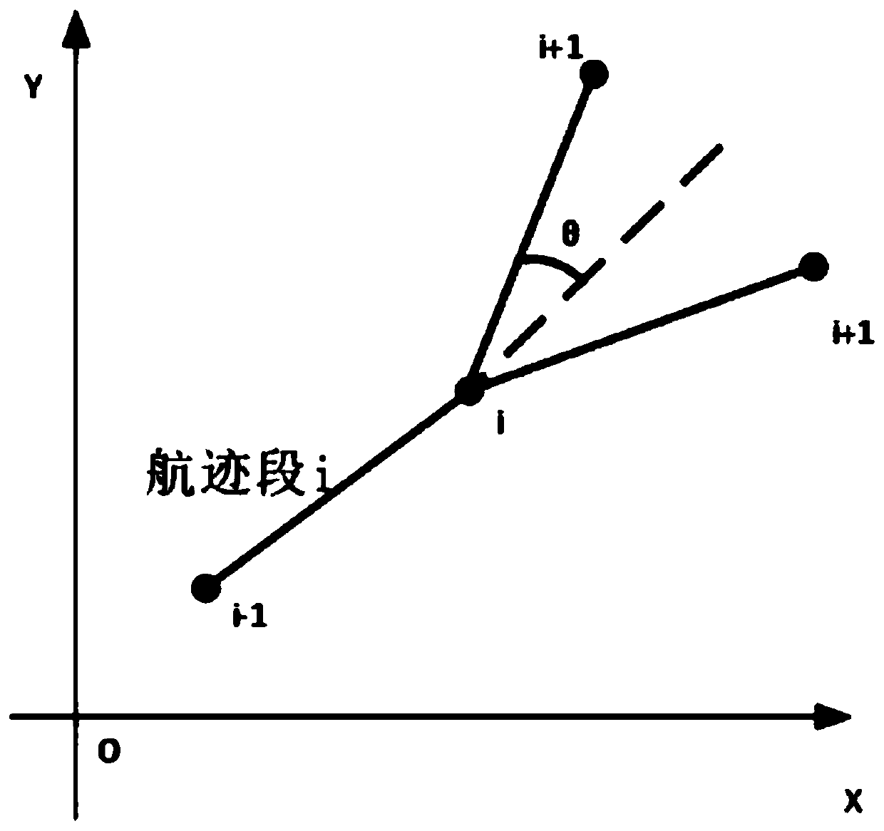
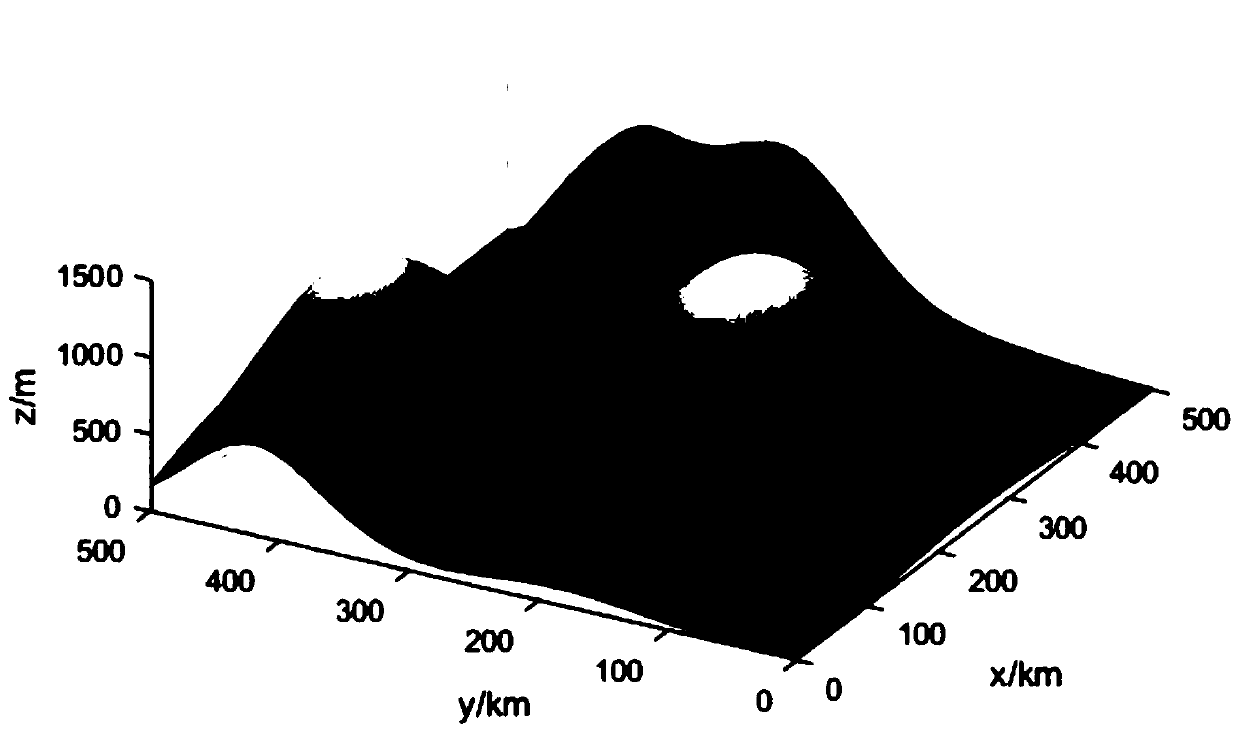
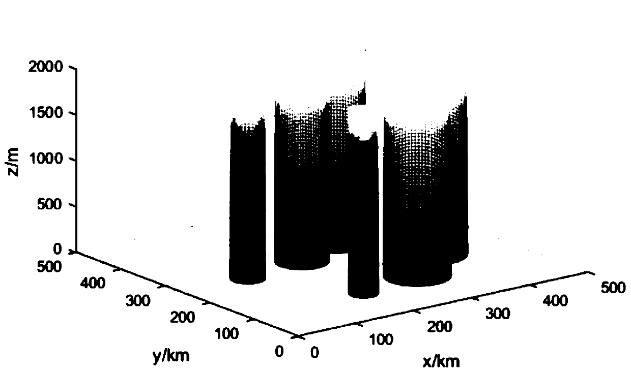
[0087] Population size: 100; maximum number of iterations: 100; maximum / minimum value of adaptive crossover probability: 0.7 / 0.1; maximum value / minimum value of adaptive mutation probability: 0.25 / 0.05; number of drones: 3; number of track segments : 5; maximum yaw angle: 60°; maximum pitch angle: 30°; minimum flight altitude: 100m; minimum turning radius: 20m; maximum flight speed: 200km / h; minimum flight speed: 50km / h; with terrain constraints Track planning is carried out in a 500km×500km×2000m three-dimensional environment threatened by the no-fly zone, and the starting point coordinates of the three drones are set to (205,59,1783), (110,122,594), (495,480,1133),

[0088] Th...


PUM


Abstract

The invention discloses a path planning method for multiple unmanned aerial vehicles to arrive at a designated place simultaneously in a three-dimensional environment, and the method comprises the steps of building a population, wherein a chromosomes represents a comprehensive flight path, and the comprehensive flight path is formed by the series connection of the flight paths of all unmanned aerial vehicles; setting the fitness of the genetic algorithm, and comprehensively evaluating the set violation degree W of the maneuverability constraint of the unmanned aerial vehicle by the total tracklength L of all unmanned aerial vehicles, the difference degree T of arrival time of different unmanned aerial vehicles and the track; and optimizing the chromosome by adopting the genetic algorithm,and obtaining an optimal chromosome after the iteration of the genetic algorithm, and decomposing the optimal chromosome to obtain the track of each unmanned aerial vehicle. By using the method, thetechnical purposes of gathering multiple unmanned aerial vehicles and reaching the task points at the same time can be achieved, and meanwhile time errors are reduced as much as possible.

Description

technical field [0001] The invention relates to the technical field of UAV path planning and control, in particular to a path planning method for multiple UAVs to arrive at a designated place at the same time in a three-dimensional environment. Background technique [0002] UAV has the characteristics of high flexibility, low cost, high security and strong concealment. These unique superior performances make UAV technology develop rapidly and gradually become a representative technology of the world's cutting-edge technology. It is widely used in various Post-disaster rescue, urban express delivery, terrain exploration, environmental monitoring and other fields. The trajectory planning of the UAV is an important technology that affects the performance of the UAV to complete the mission; the trajectory planning refers to planning the optimal path from the starting point to the target point under the premise of considering the environmental constraints and the maneuverability ...

Claims


Application Information

Patent Timeline
Patent Type & Authority Applications(China)
IPC IPC(8): G05D1/10
CPCG05D1/101
Inventor 辛斌张皓陈杰王晴张昊王淼
Owner BEIJING INSTITUTE OF TECHNOLOGYGY
Why Eureka
Try Eureka