Crankshaft and compressor

A crankshaft and shaft technology, which is used in mechanical equipment, machines/engines, liquid variable capacity machinery, etc., can solve the problems of serious environmental pollution caused by metal casting thermoforming, high requirements for crankshaft processing equipment, and low standardization. , to achieve the effect of improving product development progress, easy processing and high standardization

Active Publication Date: 2020-06-16
ANHUI MEIZHI COMPRESSOR
View PDF12 Cites 2 Cited by
  • Summary
  • Abstract
  • Description
  • Claims
  • Application Information

AI Technical Summary

Problems solved by technology

[0002] At present, in the related technology, the crankshaft of the reciprocating compressor is generally cast in one piece for the sake of wear resistance. At the same time, the crankshaft of the reciprocating compressor casting has an eccentric structure. In order to ensure the parallelism of the main shaft and the eccentric shaft, the crankshaft processing equipment The requirements are higher and the manufacturability is poor
At the same time, when re-planning the displacement of the reciprocating compressor, it usually brings changes in parameters such as the crankshaft shaft diameter and eccentricity. According to the traditional solution, the crankshaft casting mold must be redesigned. The versatility of the mold is poor and the degree of standardization is low. In addition For the consideration of energy saving, emission reduction and environmental protection, the metal casting thermoforming process has serious pollution to the environment and consumes a lot of energy

Method used


Image

  • Crankshaft and compressor
  • Crankshaft and compressor
  • Crankshaft and compressor

Examples


Embodiment Construction

[0058] In order to understand the above-mentioned purpose, features and advantages of the present invention more clearly, the present invention will be further described in detail below in conjunction with the accompanying drawings and specific embodiments. It should be noted that, in the case of no conflict, the embodiments of the present application and the features in the embodiments can be combined with each other.

[0059] In the following description, many specific details are set forth in order to fully understand the present invention. However, the present invention can also be implemented in other ways than described here. Therefore, the protection scope of the present invention is not limited by the specific implementation disclosed below. Example limitations.

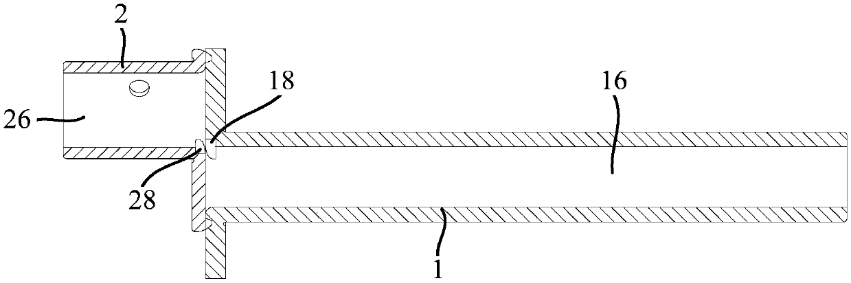
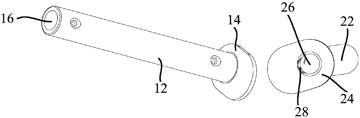
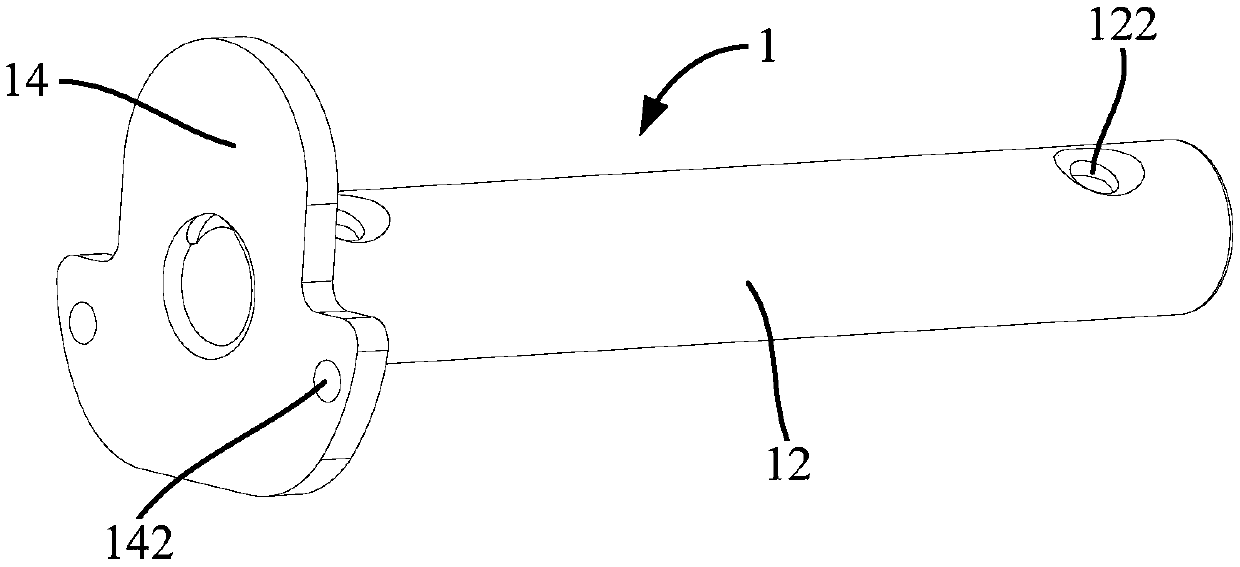
[0060] Refer below Figure 1 to Figure 5 A crankshaft provided according to some embodiments of the present invention will be described.

[0061] Such as Figure 1 to Figure 5 As shown, the embodiment of t...


PUM


Abstract

The invention provides a crankshaft and a compressor. The crankshaft comprises a first shaft and a second shaft which are arranged in a split mode, wherein the second shaft is eccentrically arranged on the end face of the first shaft; the first shaft and/or the second shaft are/is formed through forging and pressing, and/or the second shaft is eccentrically welded to the end face of the first shaft in an electric resistance welding mode. According to the scheme, the crankshaft is arranged to be the two split shafts, and in this way, the eccentric distance of the crankshaft can be adjusted by changing the relative placement positions of the first shaft and the second shaft during arrangement so that the universality of the crankshaft can be better, the standardization degree of the crankshaft is higher, meanwhile, the machining cost of the crankshaft can be saved, and the product development progress can be promoted; meanwhile, the first shaft and/or the second shaft are/is formed through forging and pressing, so that the crankshaft is simple to form and easy to machine, and machining of the crankshaft is more energy-saving and environment-protecting; and the first shaft and the second shaft are arranged together in an electric resistance welding mode, so that the connection quality between the first shaft and the second shaft is better, the connection process is more convenient, and the efficiency is higher.

Description

technical field [0001] The invention relates to the field of crankshafts, more specifically, to a crankshaft and a compressor. Background technique [0002] At present, in the related technology, the crankshaft of the reciprocating compressor is generally cast in one piece for the sake of wear resistance. At the same time, the crankshaft of the reciprocating compressor casting has an eccentric structure. In order to ensure the parallelism of the main shaft and the eccentric shaft, the crankshaft processing equipment The requirements are higher and the manufacturability is poor. At the same time, when re-planning the displacement of the reciprocating compressor, it usually brings changes in parameters such as the crankshaft shaft diameter and eccentricity. According to the traditional solution, the crankshaft casting mold must be redesigned. The versatility of the mold is poor and the degree of standardization is low. In addition For the consideration of energy saving, emiss...

Claims


Application Information

Patent Timeline
Patent Type & Authority Applications(China)
IPC IPC(8): F04B39/00
CPCF04B39/00
Inventor 孟超宋东东严志奇
Owner ANHUI MEIZHI COMPRESSOR
Why Eureka
Try Eureka