
Luggage case
A suitcase and box body technology, applied in the field of suitcases, can solve the problems of suitcase damage, easy collision with people, suitcase dumping, etc., and achieve the effect of avoiding moving around
- Summary
- Abstract
- Description
- Claims
- Application Information
AI Technical Summary
Problems solved by technology
Method used
Image

Examples
Embodiment Construction
[0014] In order to facilitate understanding of the present invention, the present invention will be further described below in conjunction with the accompanying drawings.
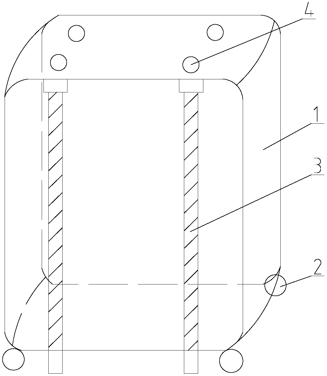
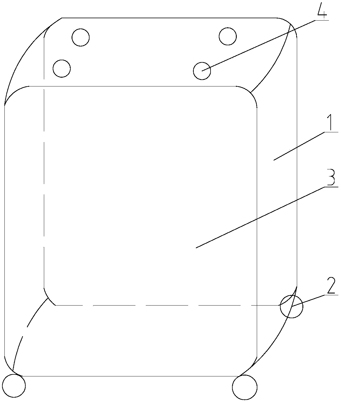
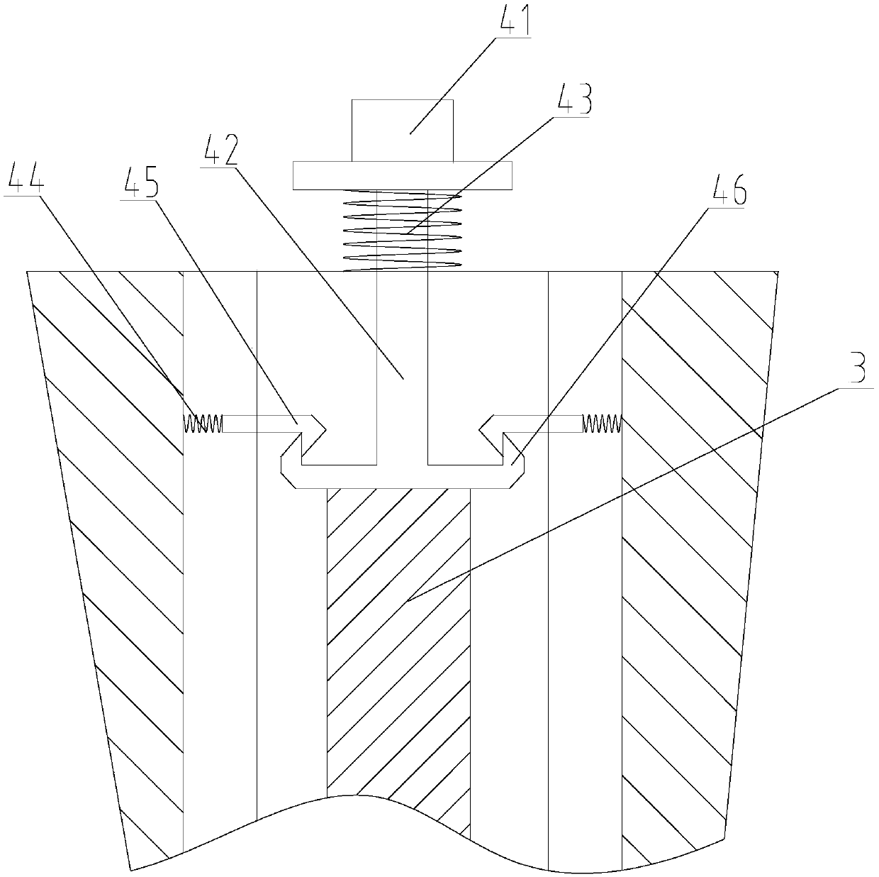
[0015] In the suitcase of the present invention, a telescopic rod 3 is provided in the case body 1, and a push-type spring structure 4 is provided on the top of the case body 1. The upper end of the telescopic rod 3 is connected with the push-type spring structure 4, and the bottom of the case body 1 Be provided with the through hole that can extend telescopic rod 3, as figure 1 and figure 2 As shown, by pressing the push-type spring structure 4, the lower end of the telescopic rod 3 can be stretched out from the bottom of the box body 1, and the box body 1 is supported by the telescopic rod 3, so that the universal wheel 2 at the bottom of the box body 1 is suspended, and the universal wheel 2. If it is not in contact with the ground after being suspended, the box body 1 will not move around, and the tel...
PUM
 Abstract
Description
Claims
Application Information