Laser cutting device with workpiece positioning function

A laser cutting and workpiece technology, applied in auxiliary devices, laser welding equipment, welding/cutting auxiliary equipment, etc., can solve the problems that other parts of the workpiece cannot be used, increase production costs, waste workpieces, etc.

Inactive Publication Date: 2020-09-25
DONGGUAN UNIV OF TECH
View PDF6 Cites 1 Cited by
  • Summary
  • Abstract
  • Description
  • Claims
  • Application Information

AI Technical Summary

Problems solved by technology

[0004] The object of the present invention is to provide a laser cutting device with workpiece positioning to solve the problem that other positions of the workpiece cannot be used in the above background technology, which not only wastes the workpiece but also reduces and increases the production cost.

Method used


Image

  • Laser cutting device with workpiece positioning function
  • Laser cutting device with workpiece positioning function
  • Laser cutting device with workpiece positioning function

Examples


Embodiment Construction

[0027] The technical solutions in the embodiments of the present invention will be clearly and completely described below in conjunction with the accompanying drawings in the embodiments of the present invention. Obviously, the described embodiments are only some of the embodiments of the present invention, not all of them. Based on The embodiments of the present invention and all other embodiments obtained by persons of ordinary skill in the art without making creative efforts all belong to the protection scope of the present invention.

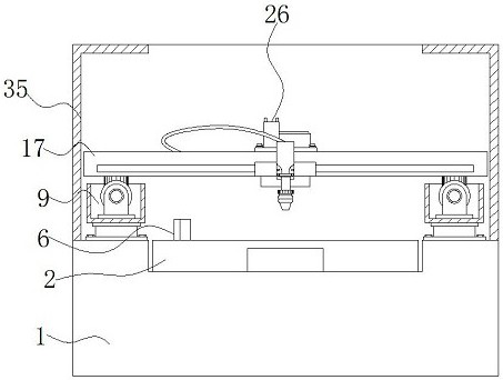
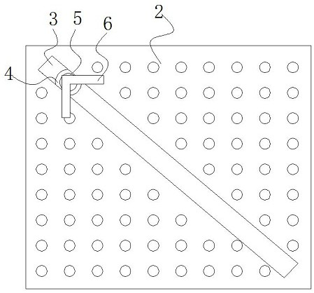
[0028] see Figure 1-5 , the present invention provides a technical solution: a laser cutting device with workpiece positioning, including a chassis base 1, a workbench 2 is installed at the upper middle groove of the chassis base 1, and a chute is provided on the upper surface of the workbench 2 3. A slider 4 is installed inside the chute 3, and a locator 5 is installed in the middle of the upper surface of the slider 4. The upper surface o...


PUM


Abstract

The invention discloses a laser cutting device with a workpiece positioning function. The laser cutting device comprises a case base. A workbench is mounted in a groove in the middle of the upper portion of the case base. Supports are symmetrically arranged on the upper surface of the case base and located on the center lines of the two sides of the workbench. A control motor is mounted on the surface of the left side of a first rack. Clamping grooves are formed in the surfaces of the two sides of a second rack. A stepping motor is mounted on the upper portion of the interior of the left sideof the second rack. Pulleys are mounted in the clamping grooves and located below clamping blocks. The lower surfaces of the clamping blocks are connected with signal receivers. A hood is mounted on the upper portion of the case base. According to the laser cutting device, the first rack and the second rack are arranged on the surface of the case base; through the arrangement of the first rack, the second rack can be conveniently driven to slide front and back; and meanwhile, through the arrangement of the second rack, a laser cutting machine can be conveniently driven to slide left and right,and thus a spray head can be prepared to be aligned with a workpiece on the workbench.

Description

technical field [0001] The invention relates to the technical field of laser cutting equipment, in particular to a laser cutting device with workpiece positioning. Background technique [0002] Laser is a kind of light. Like other natural light, it is produced by the transition of atoms (molecules or ions, etc.), but it is different from ordinary light in that laser only relies on spontaneous emission in the initial very short time, and the subsequent process is completely controlled by The laser radiation is determined, so the laser has a very pure color, almost no divergent directionality, extremely high luminous intensity and high coherence, and the laser laser cutting machine focuses the laser emitted from the laser into a high Laser beam with high power density, the laser beam is irradiated on the surface of the workpiece to make the workpiece reach the melting point or boiling point, and at the same time, the high-pressure gas coaxial with the beam will blow away the m...

Claims


Application Information

Patent Timeline
Patent Type & Authority Applications(China)
IPC IPC(8): B23K26/142B23K26/38B23K26/70B23K37/04B23K37/02
CPCB23K26/38B23K37/006B23K37/0211B23K37/04B23K26/142B23K26/702
Inventor 肖力张嵘新何楚亮
Owner DONGGUAN UNIV OF TECH
Why Eureka
Try Eureka