Waste heat recovery device for coating environment-friendly mechanical equipment

A technology of waste heat recovery equipment and mechanical equipment, applied in heat exchange equipment, lighting and heating equipment, heat exchangers, etc., can solve the problems of less waste heat recovery, less heat conduction pipes, and short residence time of hot air heat conduction pipes.

Inactive Publication Date: 2020-10-27
北京春亿东来广告有限公司
View PDF7 Cites 3 Cited by
  • Summary
  • Abstract
  • Description
  • Claims
  • Application Information

AI Technical Summary

Problems solved by technology

[0003] Based on the inventor's discovery above, the waste heat recovery equipment of an existing coating environmental protection mechanical equipment mainly has the following disadvantages, such as: when the air valve is opened to ventilate the drying box, since the air flow also contains a large amount of The heat is absorbed by the hot air flowing through the heat pipe, and the length of the hot air in the heat pipe is short, so that the hot air stays in the heat pipe for a short time, resulting in less heat absorbed by the guide heat pipe, resulting in less waste heat recovery. few cases

Method used


Image

  • Waste heat recovery device for coating environment-friendly mechanical equipment
  • Waste heat recovery device for coating environment-friendly mechanical equipment
  • Waste heat recovery device for coating environment-friendly mechanical equipment

Examples


Embodiment 1

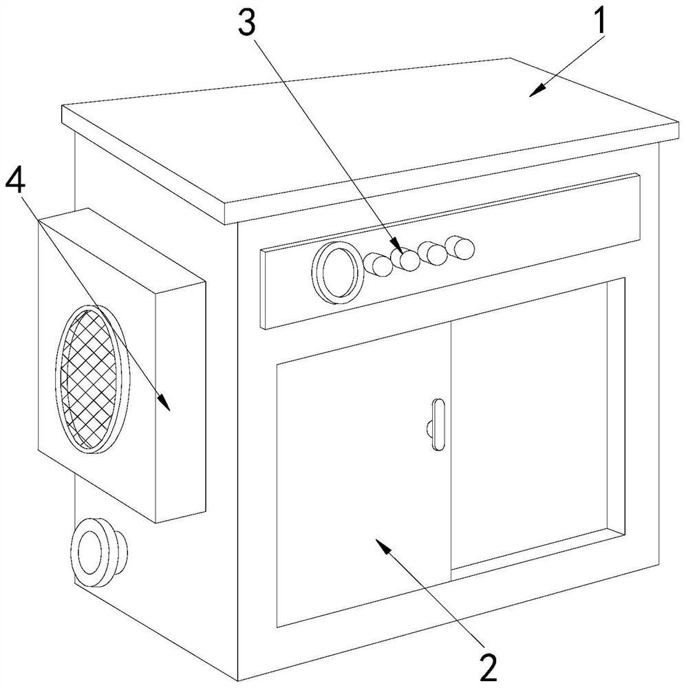
[0026] Example 1: Please refer to Figure 1-Figure 5 , the specific embodiments of the present invention are as follows:

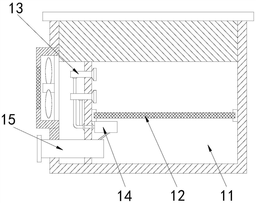
[0027] Its structure includes a main body 1, a box door 2, a control button 3, and a fan 4. The front end of the main body 1 is provided with a box door 2. The control button 3 is located at the upper end of the box door 2. At the side end, the main body 1 includes a drying box 11, a carrier plate 12, an air inlet 13, a circulation pipe 14, and a ventilation valve 15. The carrier plate 12 is installed horizontally inside the drying box 11, and the air inlet 13 Set at the side end of the drying box 11, the circulation pipe 14 is set at the lower end of the air inlet 13 and connected to the bottom of the air inlet 13, the ventilation valve 15 is installed at the bottom of the drying box 11, and runs through in subject 1.

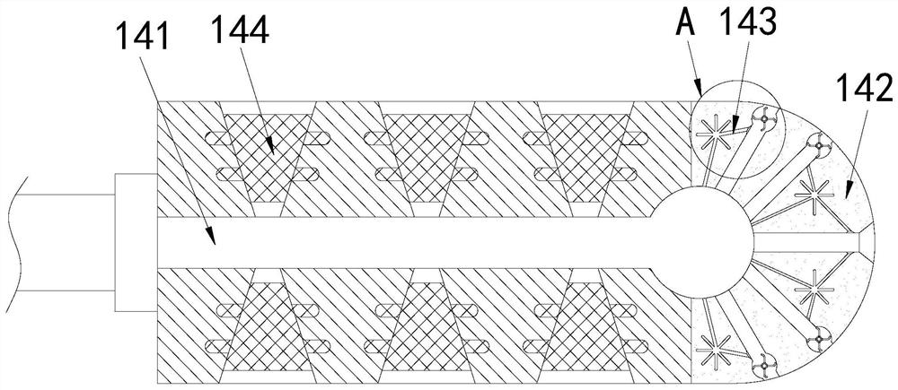
[0028] The circulation pipe 14 includes a ventilation groove 141, a heat conduction head 142, a heat conduction device 143, and a heat ...

Embodiment 2

[0032] Example 2: Please refer to Figure 6-Figure 8 , the specific embodiments of the present invention are as follows:

[0033] The heat-absorbing block 144 includes a heat-absorbing hole b1, an air guide block b2, and a heat-absorbing groove b3. There are more than five heat-absorbing holes b1, which are scattered from the bottom to the top. The air guide block b2 is provided with ten More than one, and attached to the side end of the heat-absorbing hole b1, the air-guiding block b2 is provided with four, and installed in pairs on the side end of the heat-absorbing block 144, the air-guiding block b2 is triangular in shape, It is beneficial to allow the airflow to flow back and forth in the heat absorption hole b1 and increase the contact time of the airflow with the heat absorption block 144 .

[0034] The heat-absorbing groove b3 includes a return groove b31, a perforation b32, a windshield block b33, and a diversion hole b34. One group is respectively arranged at the u...


PUM


Abstract

The invention discloses a waste heat recovery device for coating environment-friendly mechanical equipment. The device structurally comprises a body, a box door, a control button and a fan, wherein the front end of the body is provided with the box door, the control button is located at the upper end of the box door, the fan is arranged at the side end of the body, the body comprises a drying box,a carrier plate, an air inlet, a circulation tube and a scavenging air valve, the circulation tube comprises a vent groove, a heat conduction head, a heat conduction device and a heat absorbing block, the heat conduction device comprises an airflow groove, a heat conduction groove, a rotation shaft and a blade, and the blade comprises a blade body, a through hole and a rubber sheet. According tothe device, the blade with an arch-shaped tail end in the heat conduction device is used for centrally guiding airflow, so that the blade drives the rotation shaft to rotate rapidly, the flowing airflow is guided into the heat conduction groove, a contact area between air and the heat conduction head can be increased by the heat conduction groove which is extended from the middle to the outer end,absorption of heat in the air is accelerated, and the situation that a large amount of heat-carrying air is directly discharged during air exchange, and resource wasting is caused is avoided.

Description

technical field [0001] The invention relates to the field of environmental protection, in particular to waste heat recovery equipment for coating environmental protection mechanical equipment. Background technique [0002] When the waste heat recovery device is applied to the textile coating machine, after the interlining is coated with dye, the dye printed on the interlining needs to be dried through the drying box, and the drying box dries the interlining through hot air. After the hot air is in contact with the interlining, it will follow the flowing airflow and be discharged from the exhaust port. Therefore, it is necessary to use waste heat recovery equipment to recycle the hot air that has been in contact with the interlining and has waste heat. When the hot air is recycled, due to the hot air If it is recycled in the drying box, the air in the drying box needs to be replaced regularly, otherwise the coated interlining will have an increased odor. [0003] Based on th...

Claims


Application Information

Patent Timeline
Patent Type & Authority Applications(China)
IPC IPC(8): F28D21/00F28F13/12
CPCF28D21/0014F28F13/12
Inventor 郑清飞
Owner 北京春亿东来广告有限公司
Why Eureka
Try Eureka