Circuit and method for indicating power supply by applying double-color light-emitting diode and oximeter

A technology of light emitting diodes and power indication, applied in battery circuit devices, circuit monitoring/indication, circuit devices, etc., can solve the problems of not supporting online charging, battery dead, negligent display, etc., to achieve the effect of eliminating psychological pressure

Pending Publication Date: 2021-01-29
GUANGDONG GENIAL TECH CO LTD
View PDF0 Cites 0 Cited by
  • Summary
  • Abstract
  • Description
  • Claims
  • Application Information

AI Technical Summary

Problems solved by technology

[0005] (1) The low-voltage alarm is displayed by flickering on the LCD screen, which may easily cause trouble for users and interfere with viewing test data
[0006] (2) Although the energy column can display the battery capacity, users tend to ignore the display here when using the device, which may cause the device to automatically shut down before knowing that the battery is dead
[0007] (3) The online charging function is not supported, and the device may become unusable due to failure to replace the battery in time, especially if there is no spare battery at home, which may also increase the psychological pressure when using the product

Method used


Image

  • Circuit and method for indicating power supply by applying double-color light-emitting diode and oximeter
  • Circuit and method for indicating power supply by applying double-color light-emitting diode and oximeter
  • Circuit and method for indicating power supply by applying double-color light-emitting diode and oximeter

Examples


Embodiment Construction

[0048] In order to facilitate a better understanding of the purpose, structure, features, and effects of the present invention, the present invention will now be further described in conjunction with the accompanying drawings and specific embodiments.

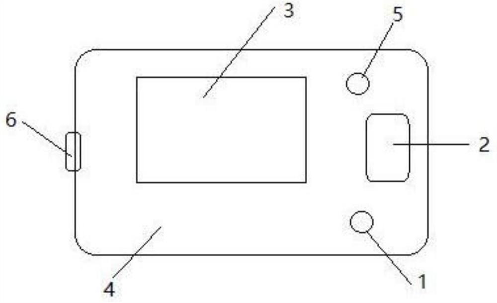
[0049] An embodiment of the present invention provides an oximeter using a two-color light-emitting diode for power indication, wherein the oximeter is a finger-clip pulse oximeter.

[0050] Such asfigure 1 As shown, the oximeter includes a body 4 and a circuit provided on the body 4, and the circuit includes a rechargeable lithium battery. The surface of the body 4 has a display screen 3, and one side of the display screen 3 is provided with a touch button 2 and two indication positions arranged at intervals, and the indication positions are provided with indicator lights 1,5. One of the indicator lights 5 is a two-color light-emitting diode for power indication, and the other indicator light 1 is used for indication of other ...


PUM

PropertyMeasurementUnit
electrical resistanceaaaaaaaaaa

Abstract

The invention discloses a circuit and a method for indicating a power supply by using a double-color light emitting diode, and an oximeter, the circuit is applied to a finger pressure type pulse oximeter, and the circuit comprises: an MCU module U1; a double-color light emitting diode D1 which is connected with the MCU module U1; a voltage detection module which is connected with the MCU module U1; a rechargeable battery module which is connected with the voltage detection module; and a power supply input module which is suitable for being connected with an external power supply, wherein the power supply input module is connected with the MCU module U1 and the rechargeable battery module, the MCU module U1 is suitable for controlling the double-color light emitting diode D1 according to the states of the power input module and the rechargeable battery module, so that the finger pressure type pulse oximeter has a visual effect which can be directly observed by human eyes. Aiming at equipment with a relatively small display screen, such as the finger clip type pulse oximeter, a user can know the power supply condition of the finger clip type pulse oximeter more intuitively by arranging the double-color light emitting diode.

Description

technical field [0001] The invention relates to a circuit, a method and an oximeter using a two-color light-emitting diode for power indication. Background technique [0002] The existing finger-clip pulse oximeters are mainly powered by AAA batteries, and do not support other methods of power supply such as lithium batteries, and the amount of power is represented by energy columns. When the battery is at low voltage, the LCD screen usually flashes. Or the prompt that the energy column has no electricity. [0003] However, because the LCD screen of the finger-clip pulse oximeter generally uses a display screen of about 1 inch, the display icons for the energy column are relatively small, and using the finger-clip pulse oximeter device is different from using a mobile phone. Generally, the usage status of the battery is not strongly concerned. Unless there is a more intuitive way of observation, it is often only when the battery is completely dead or cannot be turned on, ca...

Claims


Application Information

Patent Timeline
Patent Type & Authority Applications(China)
IPC IPC(8): H02J7/00G08B5/36
CPCA61B5/145G01R31/3646G01R31/382H02J7/0048H02J7/0049
Inventor 舒畅
Owner GUANGDONG GENIAL TECH CO LTD
Why Eureka
Try Eureka