
Gas transmission switch
A switching and gas transmission technology, applied in gaseous fuel supply/distribution, household heating, combustion methods, etc., can solve the problem that ball valves and gate valves cannot transport slag gas, and achieve the effect of convenient maintenance and reduction of manufacturing costs.
- Summary
- Abstract
- Description
- Claims
- Application Information
AI Technical Summary
Problems solved by technology
Method used
Image

Examples
Embodiment Construction
[0011] The present invention will be further described below in conjunction with accompanying drawing.
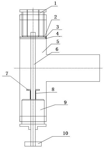
[0012] refer to figure 1 , a gas transmission switch, including a T-shaped three-way body, the two ends of the cross arm of the T-shaped three-way body 5 are respectively equipped with a bushing and a plug, and the inner end of the bushing 1 is sealed and fixed with a overlapping piece 2; the screw rod 6 is in turn After the seal passes through the plug 8 and the fixed overlapping piece 2, it is connected to the gap of the bushing 1. The movable overlapping piece 4 is fixed on the screw rod 6 and is in contact with the fixed overlapping piece 2. The fixed overlapping piece 2 and the movable overlapping piece 4 have mutual Displaced via holes; a baffle 7 is fixedly connected to the screw rod 6 above the inner end of the plug 8, and a compression spring 8 is set on the screw rod 6 between the baffle plate 7 and the inner end of the plug 9, and the screw rod 6 is in the The t...
PUM
 Abstract
Description
Claims
Application Information