Check patentability & draft patents in minutes with Patsnap Eureka AI!

Device and method for operating an impedance-variable load at the planar transformer in high-frequency operation i

A planar transformer and operating plane technology, which is applied in the direction of fixed transformer or mutual inductance, transformer/inductor coil/winding/connection, impedance network, etc., can solve the problems of reducing total efficiency, harmonic deviation, signal power loss, etc.

Inactive Publication Date: 2021-02-23
KIEFEL GMBH
View PDF0 Cites 0 Cited by
  • Summary
  • Abstract
  • Description
  • Claims
  • Application Information

AI Technical Summary

Problems solved by technology

[0014] A disadvantage of the prior art is, inter alia, that such measures for deviating the harmonics are associated with high outlays
Another disadvantage of the prior art is that such measures for deviating the harmonics always involve a loss of signal power, which reduces the overall efficiency

Method used


Image

  • Device and method for operating an impedance-variable load at the planar transformer in high-frequency operation i

Examples


Embodiment Construction

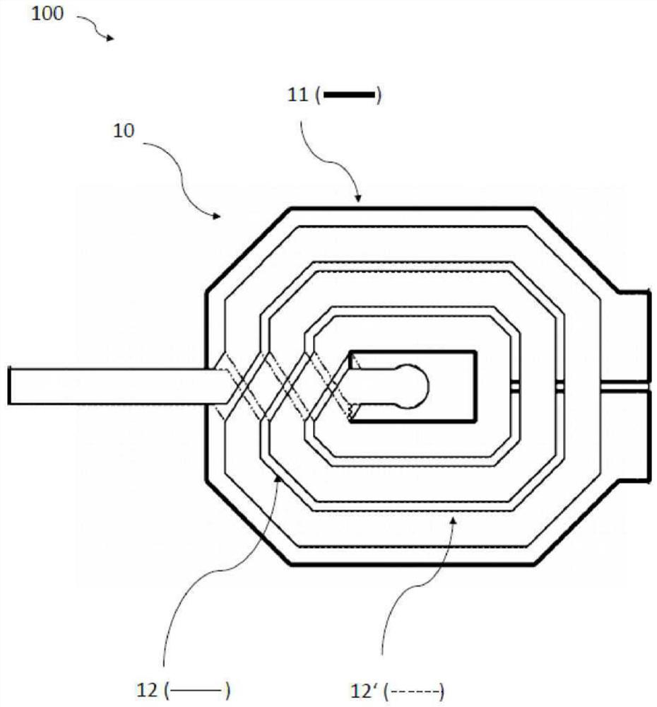
[0022] A planar transformer extending over seven layers substantially plane-parallel to each other is used as an illustrative example; in a row of consecutive layers, the layers perpendicular to each other are called first layer S1, second layer P1, third layer S2, The fourth floor P2, the fifth floor S3, the sixth floor P3 and the seventh floor S4.

[0023] For example geometrically consistent, each primary coil with a first input and a second input is arranged in three layers, a second layer P1, a fourth layer P2 and a sixth layer P3, wherein the first inputs of all primary coils are electrically short-circuited to each other , and the second inputs of all primary coils are electrically shorted to each other. The first secondary coil consists of a first coil portion T1 in the first layer S1 with a first winding number in the first winding direction and a fourth in the seventh layer S4 in the seventh layer S4 with the first winding number in the winding direction opposite to ...


PUM


Abstract

The invention relates to a method for operating an impedance-variable load at a device consisting of a planar transformer consisting of at least one primary side and at least one secondary side whichcan be operated, respectively, as the input side and the output side, said method having the step of representing a virtual HF ground in the point of symmetry of one of the secondary sides with respect to a first impedance.

Description

technical field [0001] The present invention relates to an apparatus and method for operating a variable impedance load on a planar transformer in radio frequency operation. Background technique [0002] An arrangement is disclosed in the prior art in which a signal power source is connected to a load through a transmission path. In the high power range, a low-impedance source (e.g., 1Ω) is usually connected through a higher-impedance transmission path (e.g., 50Ω) to a low-impedance load, which is usually variable (e.g., around the value of 1Ω is variable). For impedance matching, a first matching network with a (eg fixed) first impedance ratio is usually used between the source and the transmission path, and a (eg variable) second impedance ratio is used between the transmission path and the load the second matching network. The signal is transmitted from the power source to the load via the first matching network, the transmission path and the second matching network. ...

Claims


Application Information

Patent Timeline
Patent Type & Authority Applications(China)
IPC IPC(8): H03H7/38H01F19/04H03H7/09
CPCH01F19/04H03H7/09H03H7/383H01F7/064H01F27/28
Inventor 克里斯托夫·布拉姆伯格
Owner KIEFEL GMBH
Features
  • R&D
  • Intellectual Property
  • Life Sciences
  • Materials
  • Tech Scout
  • Unparalleled Data Quality
  • Higher Quality Content
  • 60% Fewer Hallucinations
Learn More