AI technical title is built by Patsnap AI team. It summarizes the technical point description of the patent document.
A joint and unit connection technology, which is applied in the field of finger devices, grippers and joint units, can solve the problem of small workspaces and achieve the effect of providing response speed
Active Publication Date: 2021-03-30
CHINA ACADEMY OF SPACE TECHNOLOGY
View PDF7 Cites 0 Cited by
Summary
Abstract
Description
Claims
Application Information
AI Technical Summary
This helps you quickly interpret patents by identifying the three key elements:
Problems solved by technology
Method used
Benefits of technology
Problems solved by technology
The present invention simplifies the structure and control link, reduces the error, and improves the degree of freedom and stiffness of the joint, but it is limited to the degree of freedom of rotation, and also has the disadvantage of small working space in practical applications
Method used
Image
Click on the blue label to locate the original text in one second.
Reading with bidirectional positioning of images and text.
Examples
Embodiment 1
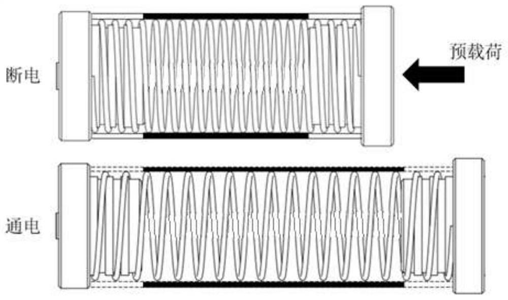
[0060] This embodiment provides a joint unit, which uses the linear drive of the cylindrical EAP driver to realize the degree of freedom of movement of the joint unit, and uses the SMA driver to realize the degree of freedom of rotation of the joint unit, which solves the problem of using EAP drive and SMA drive in the prior art. The technical problem of the small working space of the mechanical fingers.
[0061] Such as Figure 5 to Figure 7 The joint unit shown contains:
[0062] a cylindrical EAP driver, the cylindrical EAP driver comprising:
[0063] The first spring 2, the first spring 2 includes a first end and a second end;
[0064] guide rod 1, the guide rod 1 and the first spring 2 are coaxially arranged;
[0065] EAP film 8, EAP film 8 is wound several layers on the first spring 2, as Figure 6 As shown, a plurality of flexible conductive units 11 are disposed on the EAP film 8, and the flexible conductive unit 11 includes electrode lead wires 1104, the electrode...
Embodiment 2
[0093] This embodiment provides a finger-shaped device, which includes two joint units in Embodiment 1. At the connection of the joint units: the first end of the first spring of one joint unit and the second spring of the other joint unit the second end connection.
[0094] The same or different bending deformation directions of the SMA drivers of the two joint units are beneficial to increase the working space of the finger device.
Embodiment 3
[0096] This embodiment provides a gripper, comprising three joint units and palm plates in Embodiment 1, the first end of the first spring of each joint unit is rotatably connected to the palm plate, and the three joint units Evenly distributed with respect to the center of the palm plate.
[0097] When performing a grasping action, the three joint units contact the target object from different directions, and cooperate with each other to complete the grasping.
PUM
Abstract
The invention discloses a Joint unit, a finger-shaped device and a gripper. According to the joint unit, a cylindrical EAP driver and an SMA driver are combined through a connecting piece, a moving freedom degree of the joint unit is achieved through linear driving of the cylindrical EAP driver, a rotating freedom degree of the joint unit is achieved through the SMA driver, the technical problem that in the prior art, a working space of mechanical fingers driven by an EAP and an SMA is small is solved, meanwhile, due to the fact that the cylindrical EAP driver and the SMA driver are connectedin series end to end, when the joint unit is used for executing the tail end, an position, motion and mechanical inverse solution operation is simple, and a response speed can be increased.
Description
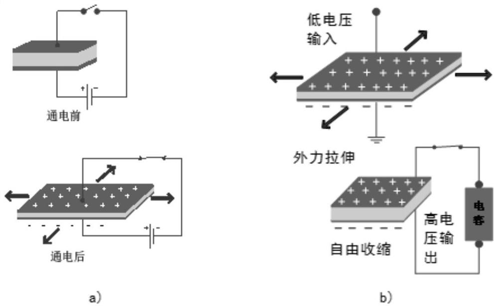
technical field [0001] The present application relates to the technical field of multi-degree-of-freedom flexible manipulators, in particular, to a joint unit, a finger device and a gripper. Background technique [0002] In recent years, while advanced drive technology has been continuously developed, many smart drive materials have been applied in the field of manufacturing new drives. According to the different power sources used, the driving technologies widely used in electromechanical systems mainly include pneumatic drive, motor\reducer drive, shape memory alloy drive (Shape Memory Alloy, SMA), piezoelectric drive and electro-deformable polymer ( electro-active polymer, EAP) driver. Among them, as a typical artificial muscle material, EAP can be used as a driver to convert electrical energy into mechanical energy, and can also convert mechanical energy into electrical energy for power generation or sensing. Compared with traditional electromagnetic and piezoelectric ...
Claims
Application Information
Patent Timeline
Application Date:The date an application was filed.
Publication Date:The date a patent or application was officially published.
First Publication Date:The earliest publication date of a patent with the same application number.
Issue Date:Publication date of the patent grant document.
PCT Entry Date:The Entry date of PCT National Phase.
Estimated Expiry Date:The statutory expiry date of a patent right according to the Patent Law, and it is the longest term of protection that the patent right can achieve without the termination of the patent right due to other reasons(Term extension factor has been taken into account ).
Invalid Date:Actual expiry date is based on effective date or publication date of legal transaction data of invalid patent.

