A C-type guide rail fall arrester

A technology of anti-fall device and guide rail, which is applied in the processing of building materials, construction, accessories of scaffolding, etc., can solve the problem of inconvenient adjustment of the height of the guide rail, improve the anti-fall response performance, facilitate installation and maintenance, and is not easy to get stuck. Effect

Active Publication Date: 2021-08-06
GUANGZHOU DAMON SECURITY TECH
View PDF0 Cites 0 Cited by
  • Summary
  • Abstract
  • Description
  • Claims
  • Application Information

AI Technical Summary

Problems solved by technology

[0003] When the wall mount is used in conjunction with the guide rail, in order to prevent the guide rail from falling freely under the influence of gravity after accidentally losing its support, an anti-fall mechanism is generally installed on the wall mount or the guide rail separately. By adjusting the forward and reverse functions of the anti-fall mechanism, the guide rail only Can run along the wall in one direction, this structure will make it inconvenient to adjust the height of the guide rail

Method used


Image

  • A C-type guide rail fall arrester
  • A C-type guide rail fall arrester
  • A C-type guide rail fall arrester

Examples


Embodiment Construction

[0030] The technical solutions in the embodiments of the present invention will be clearly and completely described below in conjunction with the embodiments of the present invention. Obviously, the described embodiments are only a part of the embodiments of the present invention, but not all of the embodiments. Based on the embodiments of the present invention, all other embodiments obtained by persons of ordinary skill in the art without creative efforts shall fall within the protection scope of the present invention.

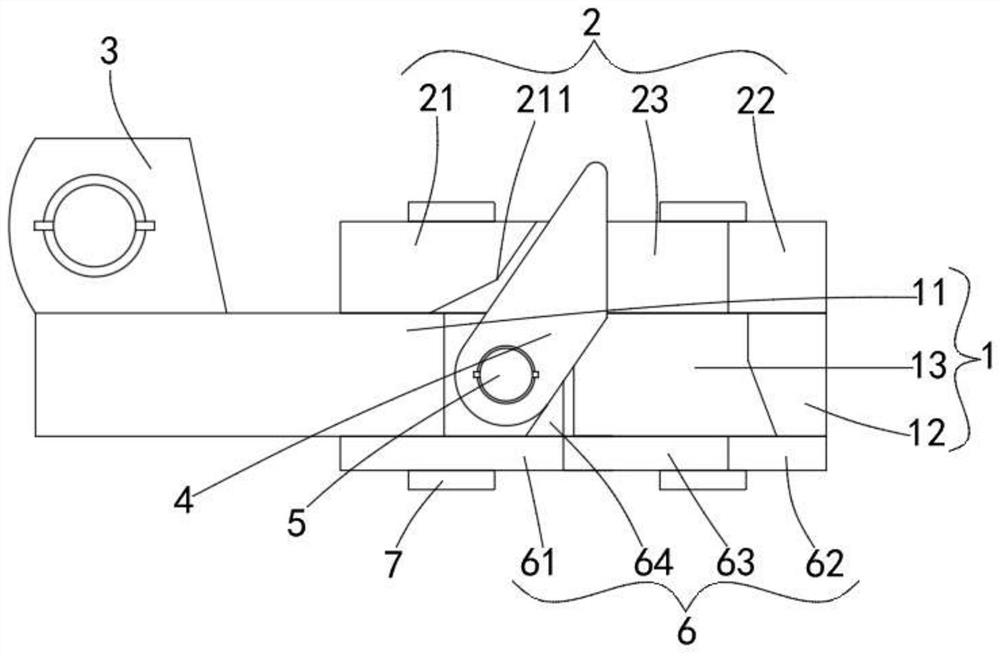
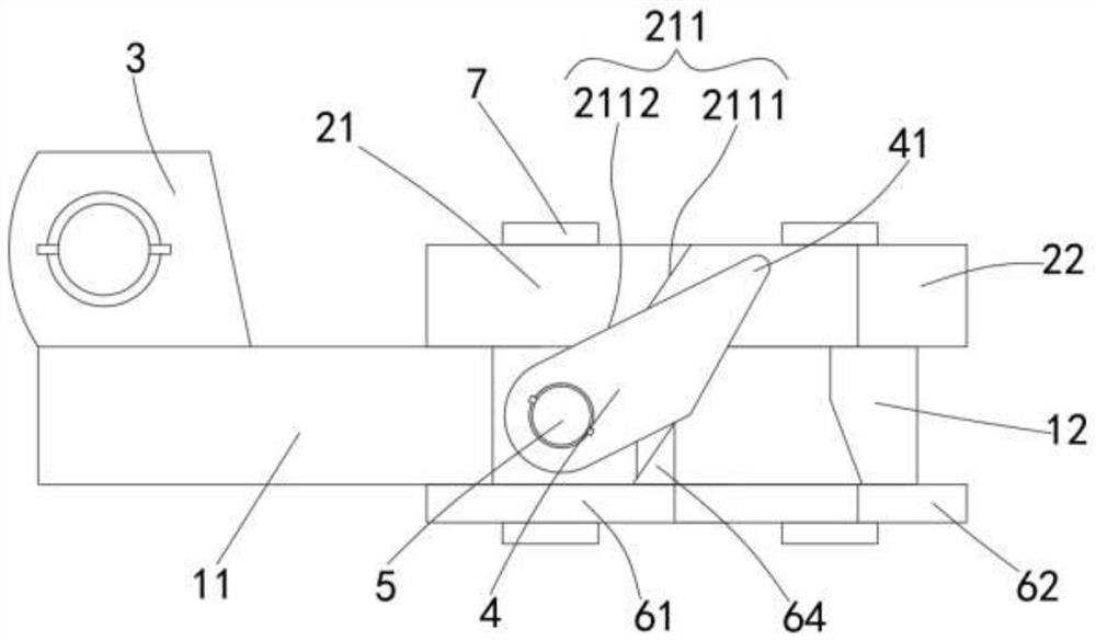
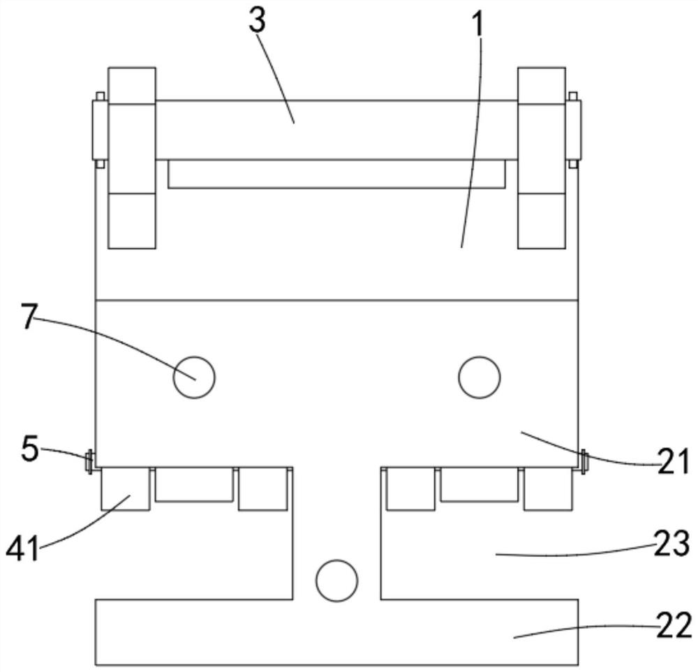
[0031] like figure 1 shown, combined with figure 2 , image 3 , Figure 4 and Figure 8 , a C-type guide rail fall arrester of the present invention includes a wall mount mechanism and a guide rail 8, the wall mount mechanism is fixedly installed on a wall, and the guide rail 8 is provided with a C-shaped opening 81, and both sides of the opening 81 have flippers The side 82 also includes the main body 1 , the first movable body 2 , the hinge mechanism 3...


PUM


Abstract

The present invention proposes a C-type guide rail fall arrester, which includes a main body, a first movable body, a hinge mechanism and a locking part. The main body includes a first fixed part and a second fixed part, and the first fixed part faces one side of the second fixed part There is a cavity on the side. The first movable body includes a first movable part and a first trigger part. The first movable part is slidably connected to the upper surface of the first fixed part and can move horizontally in the direction of the second fixed part. The locking part is located in the cavity. In the groove, the locking part has a movable end, and the movable end can rotate clockwise or counterclockwise around the horizontal line between the abutment surface and the end surface of the guide rail facing the wall; when the guide rail falls freely, through the friction force and the downward impact force It will cause the trigger part to move away from the wall, drive the movable end to screw into the first interval and approach the second fixed part, and press the movable end, so that the flange of the guide rail is fixedly clamped between the movable end and the second fixed part. Between the fixed parts, the purpose of preventing the guide rail from falling is realized.

Description

technical field [0001] The invention relates to the technical field of guide rail anti-fall, in particular to a C-type guide rail anti-fall device. Background technique [0002] Attached lifting scaffolding equipment is a new type of scaffolding technology developed rapidly at the beginning of this century, which has an important impact on the progress of construction technology in my country. It changes high-altitude operations into low-level operations, and turns suspended operations into internal operations of the frame. It has obvious low-carbon, high-tech content, and is more economical, safer and more convenient. Attached lifting scaffold refers to an external scaffold with anti-overturning and anti-fall devices that is erected at a certain height and attached to the engineering structure, relying on its own lifting equipment and devices, which can climb or descend with the engineering structure layer by layer; the attached lifting scaffold is mainly composed of It is...

Claims


Application Information

Patent Timeline
Patent Type & Authority Patents(China)
IPC IPC(8): E04G21/32E04G5/04
Inventor 薛超
Owner GUANGZHOU DAMON SECURITY TECH
Why Eureka
Try Eureka