
Power strip capable of freely typesetting and orderly taking up wires as required
A plug-in, free technology, used in devices with flexible leads, two-part connection devices, electrical components, etc., can solve problems such as economic losses, affecting people's normal walking, and inability to store wires well, and reduce the storage area. Effect
- Summary
- Abstract
- Description
- Claims
- Application Information
AI Technical Summary
Problems solved by technology
Method used
Image

Examples
Embodiment Construction
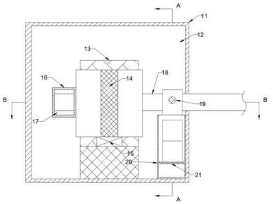
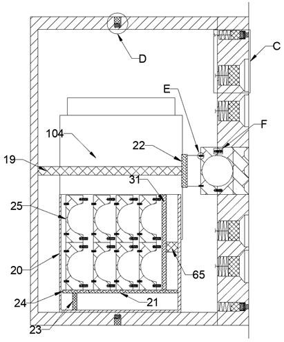
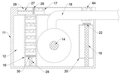
[0020] Combine below Figure 1-7 The present invention is described in detail, wherein, for the convenience of description, the orientations mentioned below are defined as follows: figure 1 The up, down, left, right, front and back directions of the projection relationship itself are the same.
[0021] A plug-in strip according to the required free typesetting and orderly winding described in conjunction with accompanying drawings 1-7, including a working box 11 and a working cavity 12 arranged in the working box 11, the working cavity 12 is up and down. The baffles 13 are arranged symmetrically, and the baffles 13 on the lower side are fixedly connected with the lower chamber wall of the working chamber 12, and the baffles 13 are mutually fixed close to the end faces, and the reels 14 are fixed together, and the reels 14 are wound with wires 18 , the baffle plate 13 on the lower side is fixedly provided with a wire winding motor 15, and the wire winding motor 15 is connected...
PUM
 Abstract
Description
Claims
Application Information