Telescopic material distributing machine

A kind of material distribution machine and telescopic technology, which is applied in shaft lining, tunnel lining, underground chamber, etc., can solve the problems of lateral force influence, large pressure loss, and many elbows, so as to achieve reasonable overall force and connect pipelines The effect of fewer bends

Pending Publication Date: 2021-06-15
HUNAN WUXIN TUNNEL INTELLIGENT EQUIP CO LTD
View PDF1 Cites 0 Cited by
  • Summary
  • Abstract
  • Description
  • Claims
  • Application Information

AI Technical Summary

Problems solved by technology

[0005] The purpose of the present invention is to provide a telescopic distribution machine, which aims to solve the problems of many elbows, large pressure loss and lateral force affecting the service life of the existing distribution machine. The specific technical solution is as follows:

Method used


Image

  • Telescopic material distributing machine
  • Telescopic material distributing machine
  • Telescopic material distributing machine

Examples


Embodiment 1

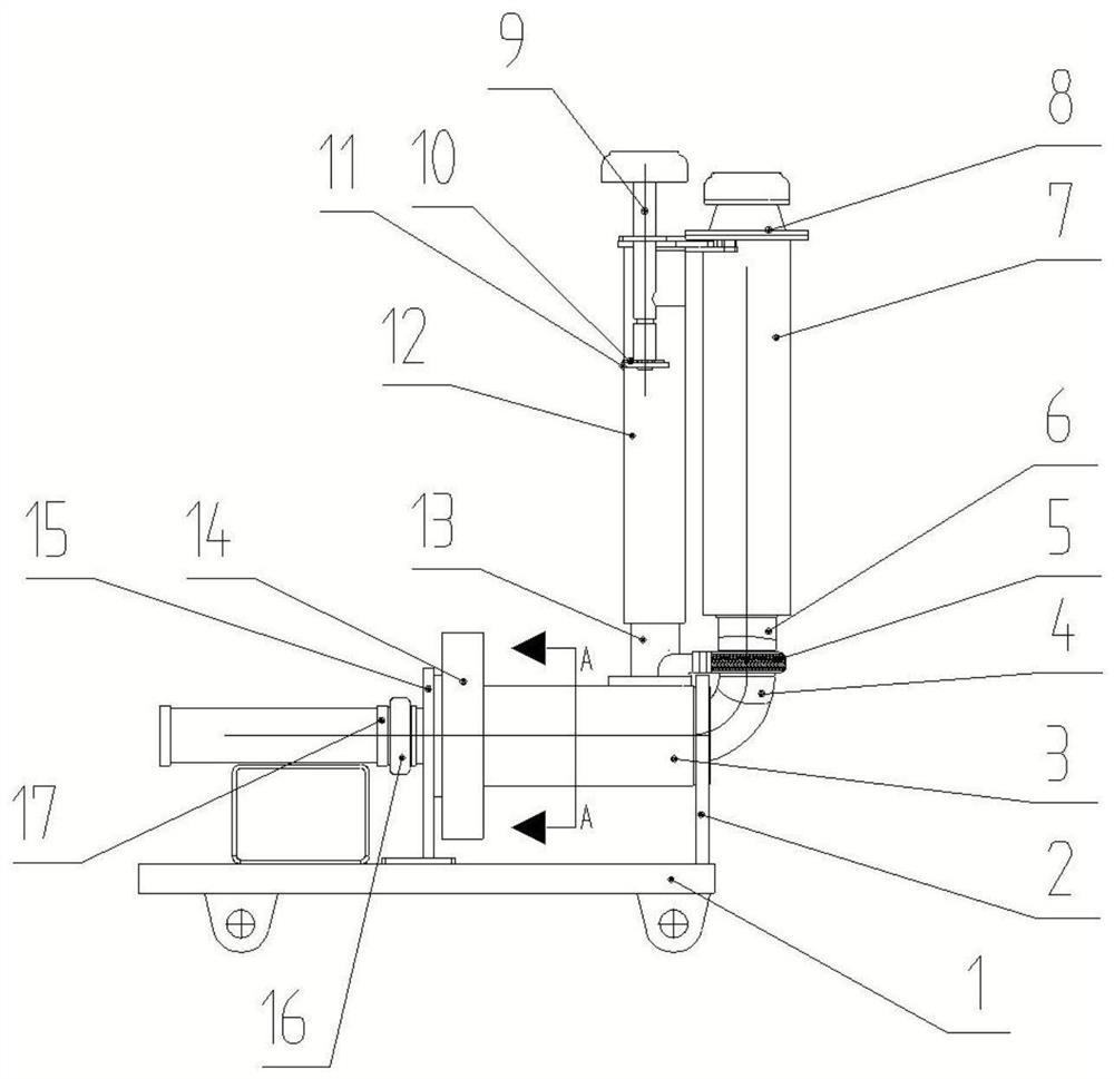
[0035] see Figure 1-5 , a telescopic distribution machine, comprising a track trolley 1, a rotating mechanism, a pouring port assembly and a cleaning port assembly, the cleaning port assembly includes a telescopic assembly and a cleaning pipe group, and the cleaning pipe group is arranged on the telescopic assembly On the rotating mechanism, the pouring port assembly includes a telescopic sleeve, the telescopic sleeve is movably connected with the telescopic assembly, and the telescopic assembly is used to drive the cleaning pipe group and the telescopic sleeve to move, and the rotating mechanism is arranged on On the track trolley 1, the rotating mechanism is used to drive the pouring port assembly and the cleaning port assembly to rotate, thereby realizing the function of rotating the cloth.

[0036] see figure 1 , the rotation mechanism includes a rotation support cylinder 3 and a rotation drive member 14, the rail trolley 1 is provided with a first support seat 2 and a s...

Embodiment 2

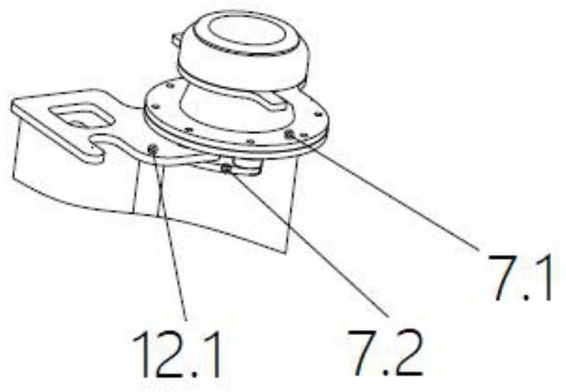
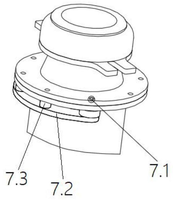
[0050] The difference between this embodiment and Embodiment 1 is that the first pipe clamp only includes a pipe clamp seat and a flexible sealing ring, and the fixed connection between the pouring mouth assembly and the rotating mechanism is realized by directly fixing the rotating support cylinder and the straight pipe. , specifically: the rotating support cylinder 3 is evenly distributed along the circumferential direction with a plurality of clamping mechanisms, and the curved straight pipe 4 is clamped by the clamping mechanisms, such as Figure 6 shown.

[0051] The clamping mechanism includes an adjusting bolt 3.1 and a pressing block 3.2. The rotating support cylinder 3 is provided with a threaded hole matching the adjusting bolt 3.1. The pressing block 3.2 is arranged at the end of the adjusting bolt 3.1 and is located Inside of barrel 3. The straight pipe is located inside the rotating support cylinder 3, and the straight pipe is compressed by the pressing block by ...

Embodiment 3

[0053] The difference between this embodiment and Embodiment 1 is that the first pipe clamp only includes a pipe clamp seat and a flexible sealing ring, and the fixed connection between the pouring mouth assembly and the rotating mechanism is realized by directly fixing the rotating support cylinder and the straight pipe. , specifically: the rotating support tube 3 is provided with a fixed plate 3.3, and the straight pipe 4 is provided with a mounting plate 4.1, and the fixed plate 3.3 and the mounting plate 4.1 are connected by a locking bolt 3.4, thereby realizing The pouring gate assembly is fixedly connected with the rotating mechanism.


PUM


Abstract

The invention provides a telescopic material distributing machine. The telescopic material distributing machine comprises a small rail car, a rotating mechanism, a pouring opening assembly and a cleaning opening assembly, wherein the cleaning opening assembly comprises a telescopic assembly and a cleaning pipe set; the cleaning pipe set is arranged on the rotating mechanism through the telescopic assembly; the pouring opening assembly comprises a telescopic casing pipe; the telescopic casing pipe is movably connected with the telescopic assembly; the telescopic assembly is used for driving the cleaning pipe set and the telescopic casing pipe to move; and the rotating mechanism is arranged on the small rail car and used for driving the pouring opening assembly and the cleaning opening assembly to rotate. According to the telescopic material distributing machine, the cleaning opening assembly and the pouring opening assembly are driven to rotate through the rotating mechanism, and vertical movement of the cleaning pipe set and the telescopic casing pipe is achieved through the telescopic assembly, so that the rotary material distributing function is achieved; and the telescopic casing pipe is movably connected with the telescopic assembly, so that small-range self-adaptive adjustment of an outer pipe of the telescopic assembly can be achieved when the outer pipe is stressed, and lateral force caused by the telescopic assembly can be eliminated.

Description

technical field [0001] The invention relates to the technical field of lining, in particular to a telescopic distributing machine. Background technique [0002] The concrete pouring of the tunnel is carried out by driving the concrete placing machine through the trolley. Most of the existing distribution machines are connected by pipelines. For example, the Chinese patent application number CN201720454209.4 discloses a concrete distribution machine. In this utility model patent, when the pipeline is stretched, there is rotation at the elbow, so as to realize the elongation of the pipeline in the length direction to match the longitudinal movement of the distribution machine; in addition, the distribution machine realizes the up and down movement of the pouring port through the rotation of the pipeline, This kind of pipeline structure has many elbows, and the pressure loss of the conveying material pipeline is large. [0003] In the prior art, there is also a form of using ...

Claims


Application Information

Patent Timeline
Patent Type & Authority Applications(China)
IPC IPC(8): E21D11/10
CPCE21D11/105
Inventor 龚俊曾勇肖国柱王慧民李超
Owner HUNAN WUXIN TUNNEL INTELLIGENT EQUIP CO LTD
Why Eureka
Try Eureka