Glass polishing device

a polishing device and glass technology, applied in the direction of manufacturing tools, metal-working machine components, portable power-driven tools, etc., can solve the problems of glass being easy to scratch or ding, not easily replaced, and vehicle windshields can become scratched, so as to achieve the effect of convenient engagemen

Active Publication Date: 2022-10-11
GLAS WELD SYST
View PDF5 Cites 0 Cited by
  • Summary
  • Abstract
  • Description
  • Claims
  • Application Information

AI Technical Summary

Benefits of technology

[0008]The device herein provides an easily engaged casing formed in a plurality of engageable components to compressibly engage the exterior of a hand held drive such as an electric or pneumatic motor or electric drill type motor. While a larger plurality of components may be formed for assembly, in a current preferred mode of the device, a first half and a second half are compressibly engageable upon an underlying hand held electric or pneumatic motor device such as a drill motor.
[0010]So engaged, the casing formed by a plurality of casing components such as a first half and a second half, is configured to communicate a fluid such as water or other fluids employed in the polishing of glass, from a pressurized fluid supply to a polishing tool or pad operatively connected to the electric motor so that it will spin. A trigger on a rear facing surface of an ergonomic handle of the engaged casing is located adjacent a raised portion of the formed casing. This is especially preferred as the raised portion provides an ergonomic handle and gripping point for one hand of the user, on an opposite side of the handle of the engaged hand held motor. This positioning provides better stability when held and used. Further, as shown herein, the edge and / or axis of the formed handle angles downward from the rear of the drill motor toward the rotating end. This allows the user to grip the formed handle and maintain their elbow at or below the level of the rotating end and tool during use, for a more comfortable use as well as a more stable use allowed by the angle of the formed handle.
[0011]Further, by positioning of the fluid trigger on a rearward facing surface of the raised portion providing the handle for gripping by one hand of the user, they may easily trigger fluid flow and cease fluid flow during a repair, without removing either hand concurrently holding the device thereby enhancing and maintaining stability during use.
[0012]Stable handling of the device herein is particularly preferred. This is because a tilting of the casing and underlying electric or pneumatic motor off of a substantially perpendicular axis, relative to the repair being attempted on glass, can cause damage to the glass rather than repairing it. As such, by positioning a secondary handle or gripping portion of the assembled casing, opposite to and in the same plane as the handle of the engaged electric motor, even pressure can be more easily applied by the user on both of the two sides of the axis of the drive powering the polishing pad engaged to rotate using the power of the electric motor. Further, the angle of the formed handle allows the user to securely grip around the outside circumference with their hand at an angle allowing them to lower the elbow of that hand during use.
[0017]It is an additional object of this invention to provide such a glass polishing device which, once engaged to a housing of a hand held electric motor, positions a projecting grip for a second hand of the user in the same plane as the handle of the underlying electric motor, and at an angle allowing a lowered elbow on the gripping hand, which also positions a fluid trigger adjacent that projecting grip thereby allowing the user to maintain a firm grip on both sides of the device during use and during concurrent actuation that triggers a fluid supply.

Problems solved by technology

A problem with most glass in buildings, vehicles, and on surfaces is the proclivity for glass to scratch or ding when impacted with a sharp instrument or when impacted by something at high speed.
Should one become scratched during shipment or installation, it is not easily replaced due to the custom configuration for the venue and window frame where it is to be installed.
Similar issues occur where custom glass surfaces cover underlying furniture or counters or other underlying surfaces which may have designs being protected by the glass.
Further, vehicle windshields can become scratched from impacts with debris or the like at vehicle speeds.
Various other limitations of the related art are known or will become apparent to those skilled in the art upon a reading and understanding of the specification below and the accompanying drawings.

Method used


Image

  • Glass polishing device
  • Glass polishing device
  • Glass polishing device

Examples


Embodiment Construction

[0028]In this description, the directional prepositions of up, upwardly, down, downwardly, front, back, top, upper, bottom, lower, left, right and other such terms refer to the device as it is oriented and appears in the drawings and are used for convenience only and such are not intended to be limiting or to imply that the device has to be used or positioned in any particular orientation.

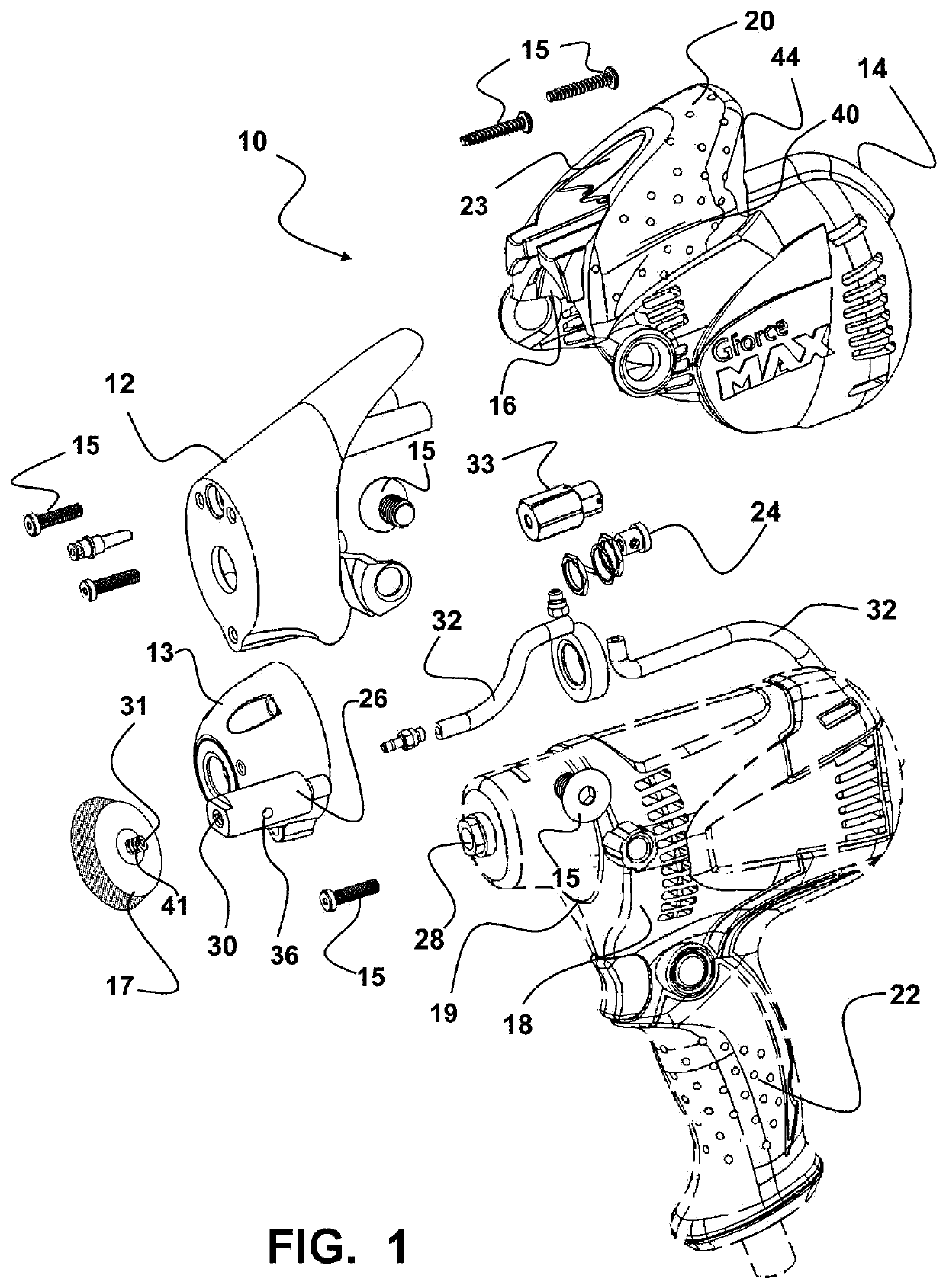
[0029]Now referring to drawings in FIGS. 1-8, wherein similar components are identified by like reference numerals, there is seen in FIG. 1, an exploded view of the device 10 showing a casing 11 formed from a plurality of casing components and having an interior surface 16 configured for a contacting engagement against an exterior housing 18 of a drill motor 19 or the like, in operative engagement to the drill motor 19. By operative engagement is meant that the interior surface 16 of the casing 11 is in contact with the exterior housing 18 of the drill motor 19 with a handle 22 of the drill motor 1...


PUM


Abstract

A glass polishing device has a casing adapted for operative engagement with the exterior surface of a powered drill motor. The casing includes a handle extending from a second side opposite an opening in an opposite first side thereof from which a handle of the engaged drill motor projects. A triggerable fluid supply is coupled to the casing and projects fluid to a tool or a section of glass being resurfaced by the tool.

Description

[0001]This application claims priority to U.S. Provisional Patent Application Ser. No. 62 / 756,484, filed on Nov. 6, 2018, which is incorporated herein in its entirety by this reference thereto.FIELD OF THE INVENTION[0002]The present device relates to the repair of scratches and dings in glass. More particularly, it relates to a glass polishing device having a casing adapted with two or more components for assembly to a compressive engagement on the exterior surface of a hand held powered drive, such as an electric or pneumatic drill motor. So engaged, the device is configured to provide an improved constant flow of fluid to a polishing pad or other polishing component which is engaged and being rotated by the electric drive concurrent with an especially secure and steady ergonomic grip for users during use.BACKGROUND OF THE INVENTION[0003]Glass is a widely employed material in buildings and vehicles throughout the world. Glass panes are employed in buildings to provide light transmi...

Claims


Application Information

Patent Timeline
Patent Type & Authority Patents(United States)
IPC IPC(8): B24B23/00B24B57/02B24B23/02
CPCB24B57/02B24B23/02B24B55/02B24B7/242B23Q11/1092B25F5/02
Inventor SCHEFFLER, DOMINIKSPOO, SHILOHLARRANAGA, EFREN
Owner GLAS WELD SYST
Why Eureka
Try Eureka