Extension tool having anchoring device

Active Publication Date: 2005-12-20
YU HSIU E
View PDF2 Cites 48 Cited by
  • Summary
  • Abstract
  • Description
  • Claims
  • Application Information

AI Technical Summary

Benefits of technology

[0008]The primary objective of the present invention is to provide an extension tool including an extendible stem adjustably attached to an elongate shaft, and having an anchoring

Problems solved by technology

However, there is no lock or anchoring device provided between the polygonal rod and the shaft, such that the polygonal rod may have a good chance to be fully pulled out of the shaft and to be disengaged from the shaft inadvertently.
Particularly, while working, the workers or the users may not pay much atten

Method used


Image

  • Extension tool having anchoring device
  • Extension tool having anchoring device
  • Extension tool having anchoring device

Examples


Embodiment Construction

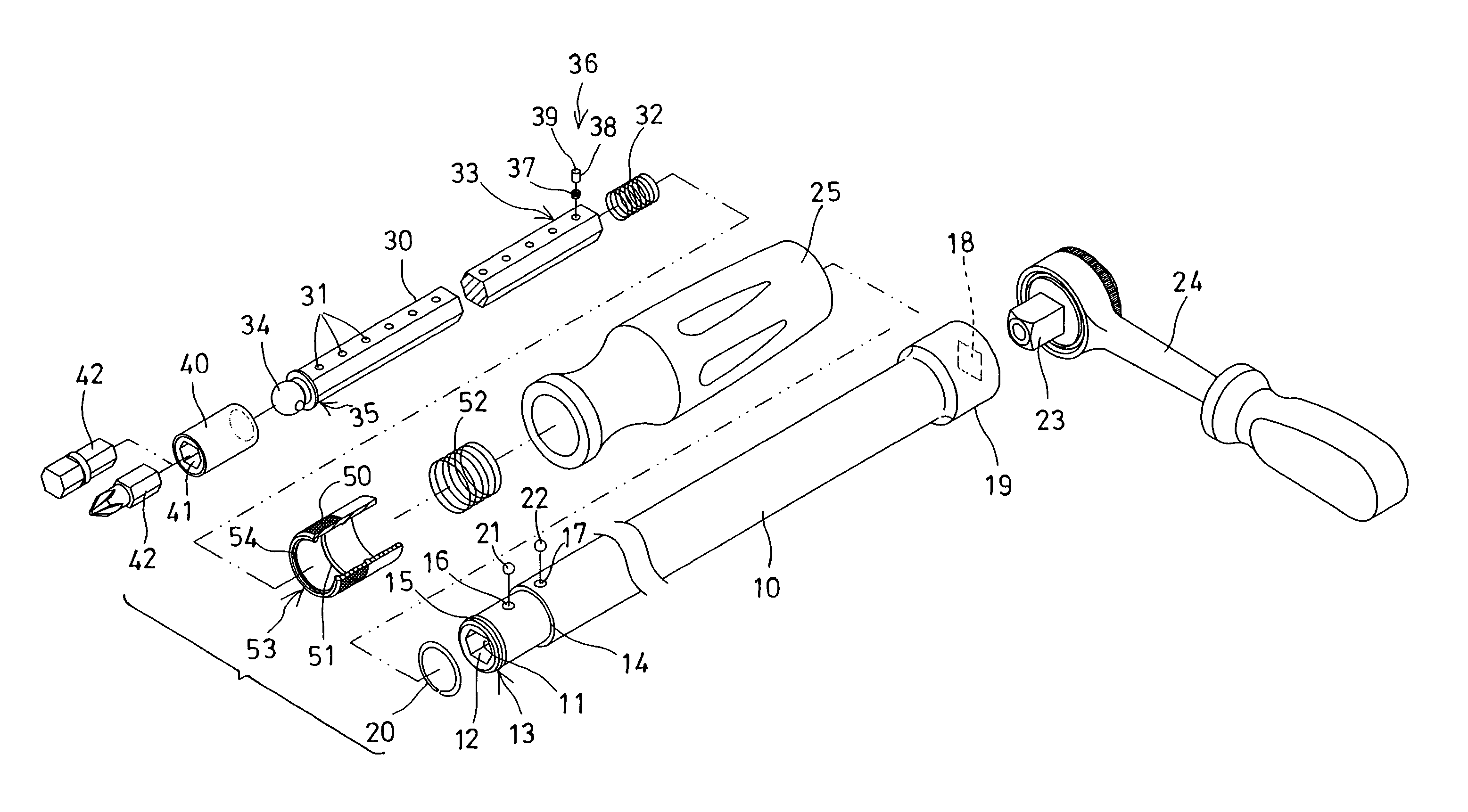
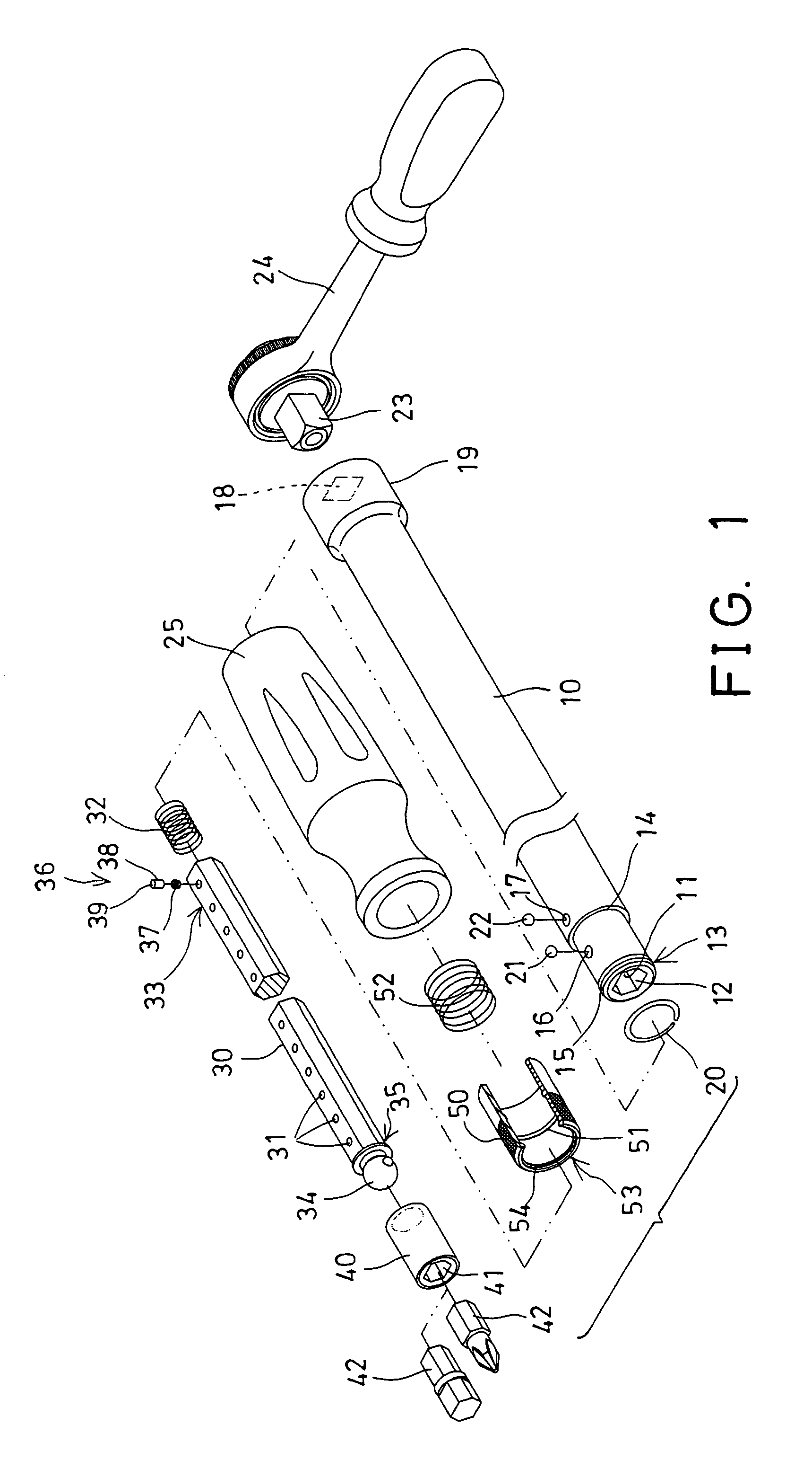
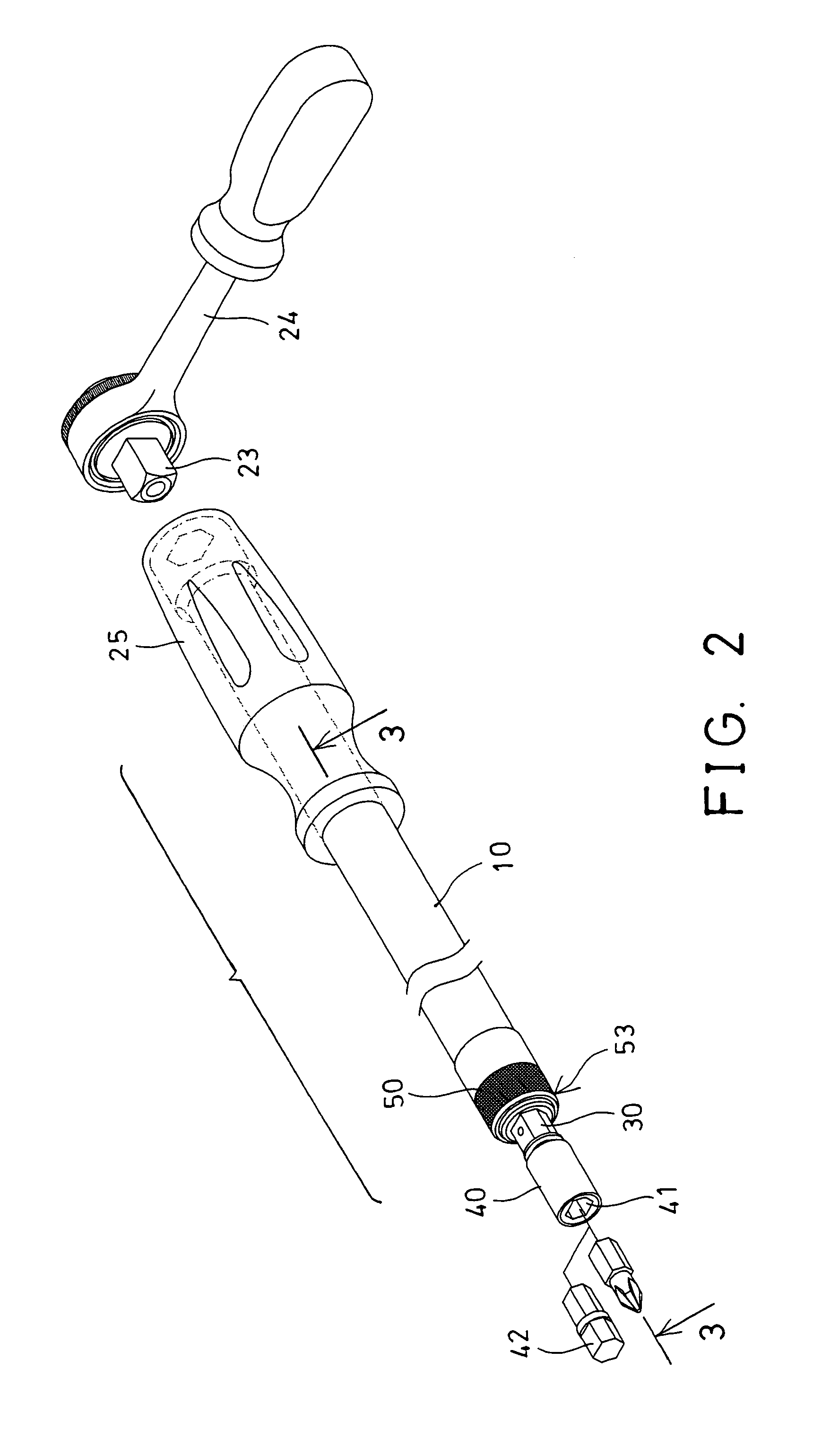
[0019]Referring to the drawings, and initially to FIGS. 1–3, an extension tool in accordance with the present invention comprises an elongate shaft 10 including a bore 11 formed therein and having a non-circular cross section and having an opening 12 formed in a front portion 13 thereof, in which the front portion 13 thereof includes a reduced outer diameter to form or define a peripheral shoulder 14 therein. The shaft 10 further includes an annular groove 15 and an orifice 16 and an aperture 17 formed in the front portion 13 thereof.

[0020]A retaining ring 20 and a ball 21 and an insert 22 may be engaged into and received in the annular groove 15 and the orifice 16 and the aperture 17 of the shaft 10 respectively. The shaft 10 further includes an engaging hole 18 formed in the rear portion 19 thereof, for engaging with or for receiving a driving shank 23 of a driving tool 24, and for allowing the shaft 10 to be rotated or driven by the driving tool 24. A handle 25 may further be pro...


PUM


Abstract

An extension tool includes a shaft having an annular groove and an orifice and an aperture formed in a front portion, to receive a retaining ring and a ball and an insert. A stem is slidably engaged into the shaft and includes a number of depressions for selectively receiving the ball, and for adjustably securing the stem to the shaft. A control ferrule is engaged onto the shaft, and has a protrusion biased to force the ball to engage into either of the depressions of the stem. A spring-biased projection is attached to a rear portion of the stem, and has a detent movable to engage into the aperture of the shaft, to lock the stem to the shaft, and to prevent the stem from being disengaged from the shaft inadvertently.

Description

BACKGROUND OF THE INVENTION[0001]1. Field of the Invention[0002]The present invention relates to an extension tool, and more particularly to an extension tool having an extendible stem adjustably attached to an elongate shaft, and having an anchoring device for anchoring the stem, and for limiting a sliding movement of the stem relative to the shaft, and for preventing the stem from being disengaged from the shaft inadvertently.[0003]2. Description of the Prior Art[0004]The applicant has developed various kinds of typical extension tools for facilitating tool driving purposes. For example, U.S. Pat. No. 6,260,452 to Yu discloses one of the typical tools comprising a polygonal rod slidably engaged in a polygonal groove of a shaft, and adjustably secured to the shaft with an outer sleeve, to allow the polygonal rod to be adjustably extended out of the shaft to different outwardly extending positions.[0005]However, there is no lock or anchoring device provided between the polygonal rod...

Claims


Application Information

Patent Timeline
IPC IPC(8): B25B23/00B25B23/16B25G1/04B25G1/06
CPCB25B23/0021B25G1/043B25G1/063
Inventor YU, HSIU-E
Owner YU HSIU E
Why Eureka
Try Eureka