Robotic surgery system including position sensors using fiber bragg gratings

a robotic surgery and position sensor technology, applied in the field of robotic surgery system including position sensors using fiber bragg gratings, can solve the problems of difficult transmission of electrical power to actuators or sensors located inside the patient's body, the inability to accurately move a distally mounted structure member, and the inability to provide for

Active Publication Date: 2011-09-15
INTUITIVE SURGICAL OPERATIONS INC
View PDF47 Cites 142 Cited by
  • Summary
  • Abstract
  • Description
  • Claims
  • Application Information

AI Technical Summary

Benefits of technology

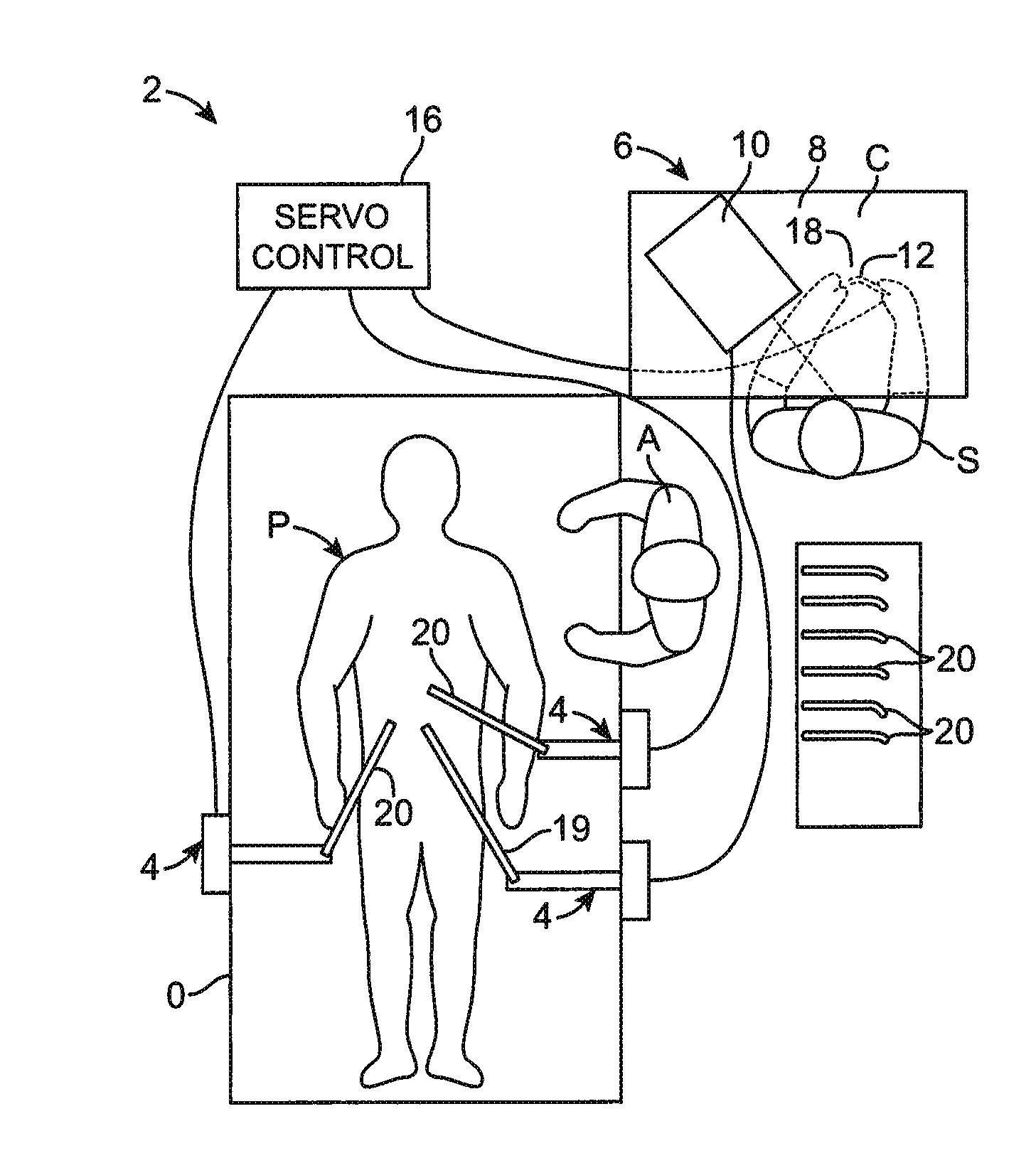
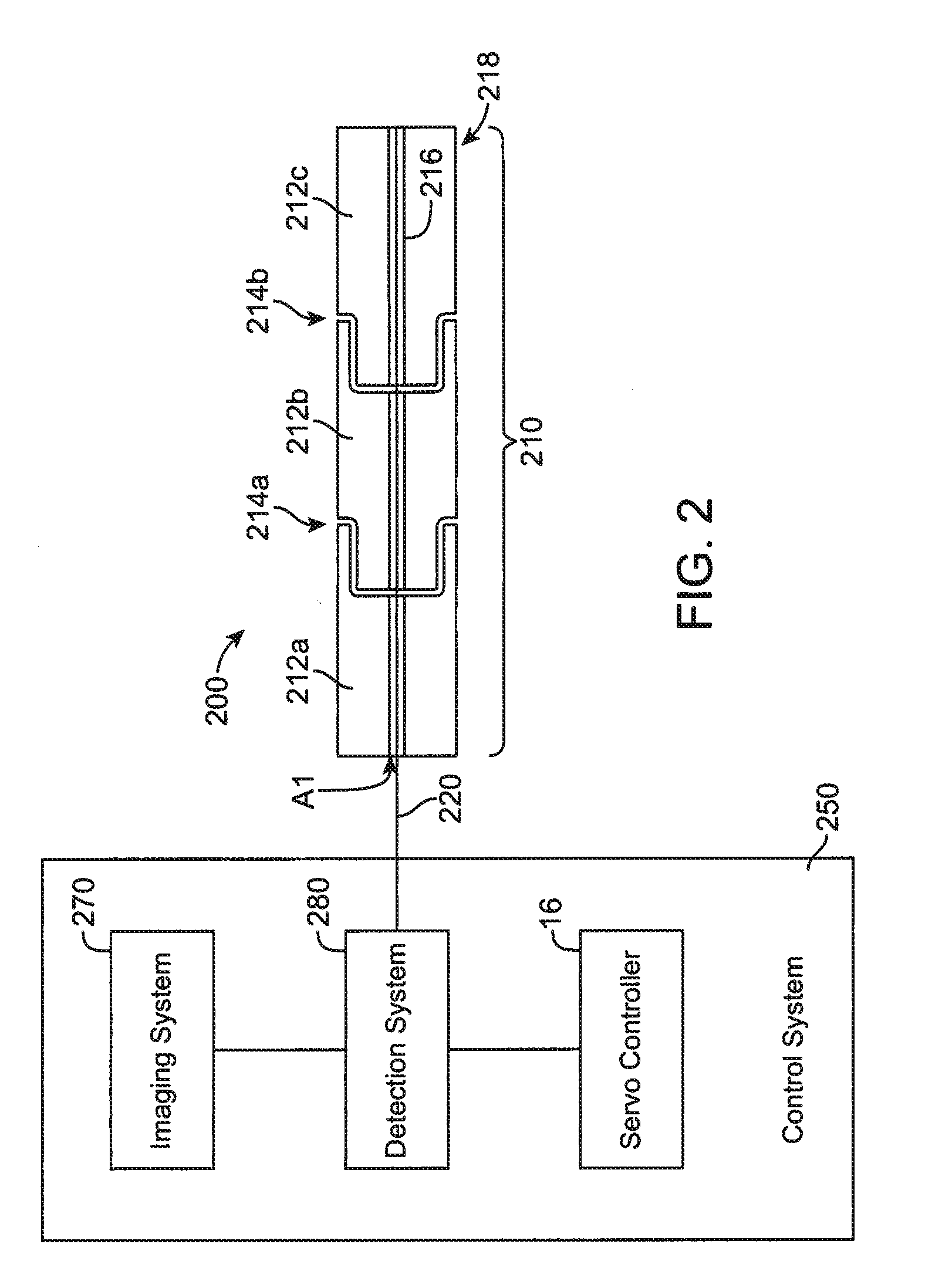
In accordance with embodiments of the present invention, a surgical instrument is provided, comprising: at least one articulatable arm having a distal end, a proximal end, and at least one joint region disposed between the distal and proximal ends; an optical fiber bend sensor provided in the at least one joint region of the at least one articulatable arm; a detection system coupled to the optical fiber bend sensor, said detection system comprising a light source and a light detector for detecting light reflected by or transmitted through the optical fiber bend sensor to determine a position of at least one joint region of the at least one articulatable arm based on the detected light reflected by or transmitted through the optical fiber bend sensor; and a control system comprising a servo controller for effectuating movement of the arm.

Problems solved by technology

Robotic manipulators, particularly small ones of the type used in minimally-invasive surgery, generally need to transmit actuation forces and sensor information some distance through the structure of the robotic device, because the mass and size of presently-available actuators (e.g., motors) and sensors (e.g., position encoders) are too large to permit them to be directly located where the force and sensing is needed.
However, the motors and sensors used are typically too large and heavy to be placed inside the patient's body.
In addition, safety concerns make transmission of electrical power to actuators or sensors located inside the patient's body problematic.
None of these force transmission means are ideal for minimally-invasive surgery, and therefore there are practical limits to the precision with which a distally mounted structure member can be moved, and the force it can provide.
For example, cables may stretch, thereby leading to errors in the distal structure position relative to the position of the proximal driving mechanism.
Compliant cables may also have significant friction with the supporting structure.
Friction is notoriously difficult to model, may behave in a time-varying way and is dependent upon any number of variables, including the position (and past history of the position) of any intermediate joints in the structure, and when combined with compliant actuation can lead to stick-slip behavior.
These errors limit the utility of the robot, limit the number of degrees of freedom that can be controlled remotely through a small structure, limit the use of the robot's state to provide haptic feedback, and are particularly severe for a flexible surgical robot which must accurately control many degrees of freedom of actuation at the end of a long, flexible structure.
While there are limits to the compensation that can be done with feedback, those limits cannot even be approached without accurate, timely information about the positions of the distally-mounted parts.
The main restriction on the applicability of feedback in these types of robotic arms is the lack of an effective means of determining the position of parts mounted at the distal end of the structure.
However, this method allows the position control loop to compensate only for error sources that occur between the actuator and the encoder.
Error sources distal to the encoder are not observed by the encoder and thus cannot be compensated.
This arrangement does not provide for compensation of errors introduced by any structures or drivetrain mechanisms that are distal to the encoders.
As a result, errors in the sensing of the orientations of intermediate links may compound along the way.
In robotically-assisted surgical systems having many degrees of freedom near the distal end, joint encoders do not offer much benefit as they are too large to be placed where the most problematic joints are located, and the connections required to transmit their position data back to the controller compete for space with the force-transmitting apparatus inside the arm.
These systems also do not provide complete position data and therefore cannot be used to compensate for some types of errors described above.
For example, GPS-based location (especially differential GPS) has been used in outdoor environments, but typically can only be applied to large structures due to the relatively poor spatial resolution.
While these systems can achieve good accuracy under ideal conditions, the accuracy rapidly degrades when metallic objects are nearby (as is the case in most surgical applications), and an external apparatus is needed to generate the field.
In addition, these sensors do not directly encode the positions of the joints or links in a structure unless a sensor is provided on each link.
Therefore, different configurations of the structure which result in the same position of the sensor are not distinguishable, which limits the use of this type of data for feedback compensation as described above.
However, these systems are only applicable to larger and slower-moving systems, such as mobile robotic platforms.
In the surgical applications considered here, these methods may be undesirable because the landmarks (e.g. patient anatomy) are not well defined and may change position as a result of disease states or during the surgical manipulations.
This approach suffers from the need to provide joint position feedback and identifiable landmarks in the viewed scene, which are also problematic in surgical applications.
These techniques suffer from various deficiencies when utilized in robotic surgical applications and do not provide the type of information desired for implementing closed-loop control of such robotic mechanisms and compensating for the deficiencies in the force-transmission means described above.
In addition, these techniques may be complex and expensive to implement.

Method used


Image

  • Robotic surgery system including position sensors using fiber bragg gratings
  • Robotic surgery system including position sensors using fiber bragg gratings
  • Robotic surgery system including position sensors using fiber bragg gratings

Examples


Embodiment Construction

In the following description, reference is made to the accompanying drawings which illustrate several embodiments of the present invention. It is understood that other embodiments may be utilized and mechanical, compositional, structural, electrical, and operational changes may be made without departing from the spirit and scope of the present disclosure. The following detailed description is not to be taken in a limiting sense, and the scope of the embodiments of the present invention is defined only by the claims of the issued patent.

The terminology used herein is for the purpose of describing particular embodiments only and is not intended to be limiting of the invention. Spatially relative terms, such as “beneath”, “below”, “lower”, “above”, “upper” and the like, may be used herein for ease of description to describe one element or feature's relationship to another element(s) or feature(s) as illustrated in the figures. It will be understood that the spatially relative terms are...


PUM

PropertyMeasurementUnit
diameteraaaaaaaaaa
diameteraaaaaaaaaa
diameteraaaaaaaaaa

Abstract

A surgical instrument is provided, including: at least one articulatable arm having a distal end, a proximal end, and at least one joint region disposed between the distal and proximal ends; an optical fiber bend sensor provided in the at least one joint region of the at least one articulatable arm; a detection system coupled to the optical fiber bend sensor, said detection system comprising a light source and a light detector for detecting light reflected by or transmitted through the optical fiber bend sensor to determine a position of at least one joint region of the at least one articulatable arm based on the detected light reflected by or transmitted through the optical fiber bend sensor; and a control system comprising a servo controller for effectuating movement of the arm.

Description

BACKGROUNDIn robotically-assisted or telerobotic surgery, the surgeon typically operates a control device to control the motion of surgical instruments at the surgical site from a location that may be remote from the patient (e.g., across the operating room, in a different room or a completely different building from the patient) or immediately adjacent to the patient. The controller usually includes one or more manually-operated input devices, such as joysticks, exoskeletal gloves or the like, which are coupled (directly or indirectly) to the surgical instruments with servo motors for articulating the instruments at the surgical site. The servo motors are typically part of an electromechanical device or surgical manipulator that supports and controls the surgical instruments that have been introduced directly into an open surgical site or through trocar sleeves into a body cavity, such as the patient's abdomen. During the operation, the surgical manipulator provides mechanical arti...

Claims


Application Information

Patent Timeline
Patent Type & Authority Applications(United States)
IPC IPC(8): A61B19/00
CPCA61B19/2203A61B19/5212A61B19/5244A61B2017/00057A61B2017/2906A61B2019/2223Y10T74/20305A61B2019/2242A61B2019/5248A61B2019/5259A61B2019/5261A61B2017/00477Y10T29/49826A61B2019/2234A61B2034/2048A61B34/20A61B2090/3614A61B34/71A61B90/30A61B90/361A61B34/37A61B2034/305A61B2034/2059A61B2034/2061A61B2034/2065Y10S901/28Y10S901/47Y10S901/09Y10S901/46A61B34/30A61B1/009A61B2017/0477B25J9/1635B25J18/06B25J19/025
Inventor LARKIN, DAVID QSHAFER, DAVID C.
Owner INTUITIVE SURGICAL OPERATIONS INC
Why Eureka
Try Eureka