Locking mechanism with two-piece washer

a locking mechanism and washer technology, applied in the field of spinal pathologies, can solve the problems of mechanical weakened predetermined locations, rest of rod seats, etc., and achieve the effect of enhancing the relative position of the rod and the fixation devi

Inactive Publication Date: 2010-01-28
INGENIUM
View PDF47 Cites 180 Cited by
  • Summary
  • Abstract
  • Description
  • Claims
  • Application Information

AI Technical Summary

Benefits of technology

[0017]Also according to an aspect of the invention, at least one lip at a bottom portion of the body may restrict the movement of the fixation device toward the bottom of the body, thereby restricting the movement of the rod seat toward the bottom of the body during the application of force by the rod to the top portion of the rod seat.
[0018]According to another aspect of the invention, a rod seat for use in a locking mechanism configured to lock the relative positions of a rod and a fixation device includes a top portion having a taper configured to receive part of the rod; a bottom portion configured to receive part of the fixation device; wherein the rod seat is configured to separate into two pieces when the rod exerts from approximately 50 lbs to approximately 2500 lbs of force on the top portion of the rod seat and the fixation device limits movement of the rod seat away from the rod; and wherein locking of the relative positions of the rod and the fixation device is enhanced following the separation of the rod seat into two pieces.

Problems solved by technology

In addition, the predetermined location may mechanically weakened compared to the remainder of the rod seat, such as by being thinned, notched, grooved, scored or perforated.

Method used


Image

  • Locking mechanism with two-piece washer
  • Locking mechanism with two-piece washer
  • Locking mechanism with two-piece washer

Examples


Embodiment Construction

[0030]The invention relates to novel locking mechanisms and methods for locking the relative positions of a rod and a fixation device. The locking mechanisms provide improved locking between a rod and the head of a fixation device, such as a screw. The various locking mechanisms disclosed herein include either a rod seat or a washer disposed between the rod and the fixation device.

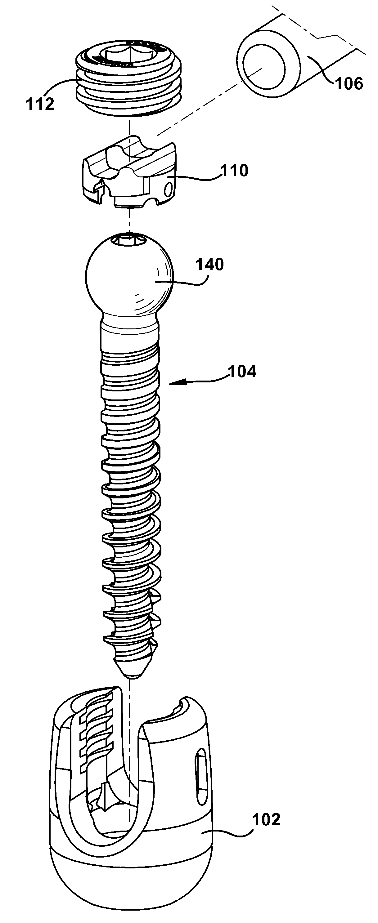
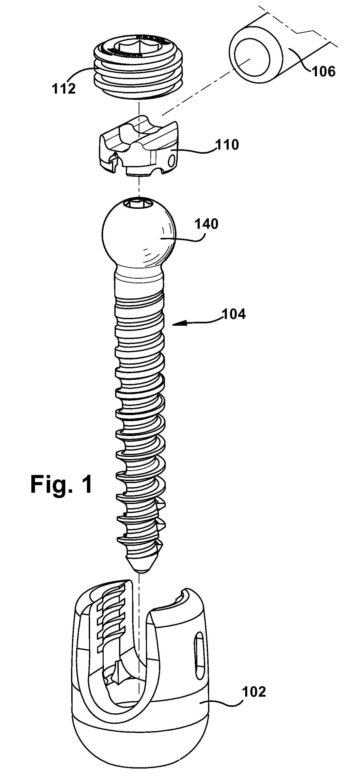
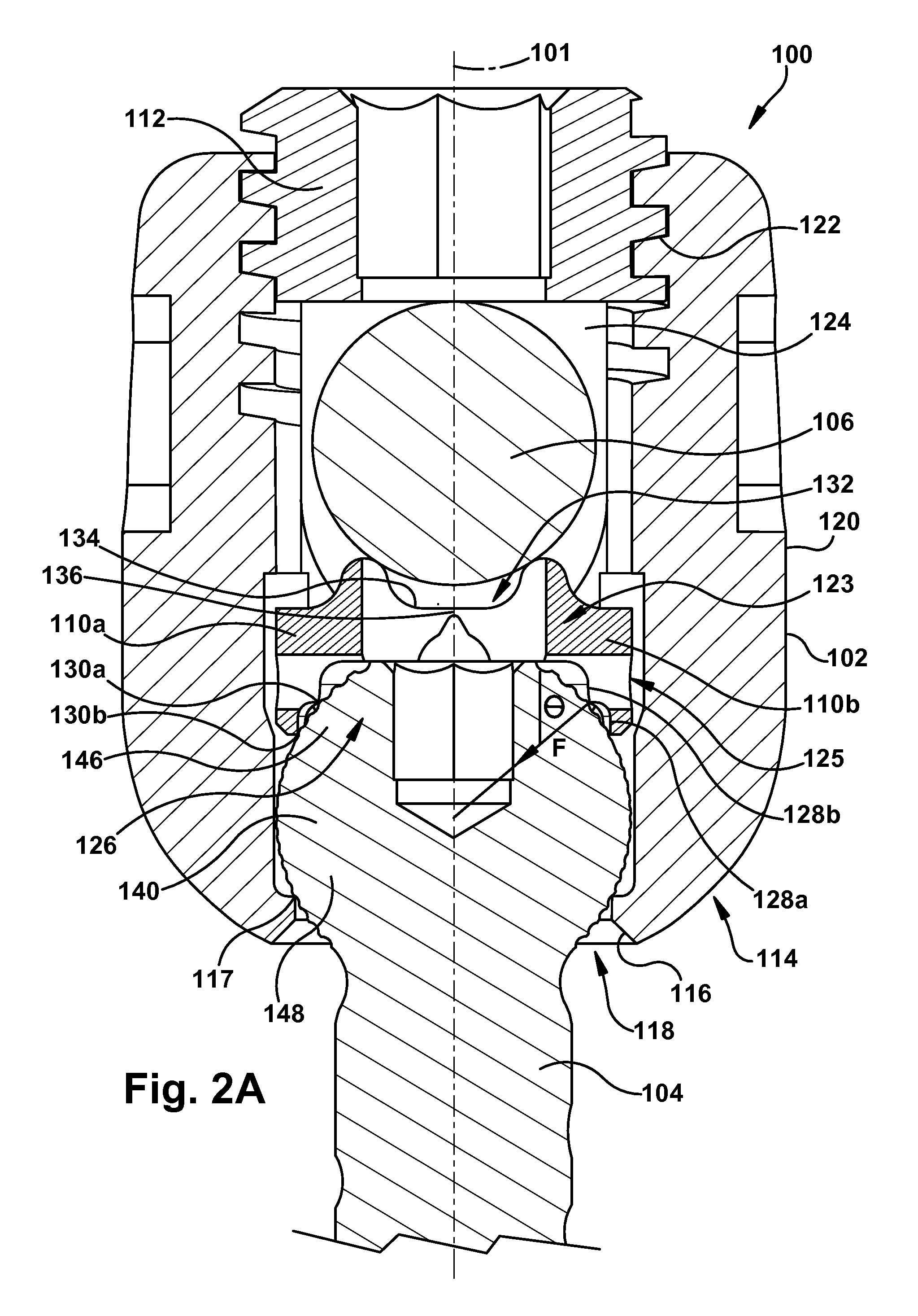
[0031]Turning initially to FIGS. 1 and 2A-B, FIG. 1 shows an exploded perspective view of a locking mechanism, and FIGS. 2A-B show cross sectional views of the locking mechanism of FIG. 1 in unlocked and locked positions. The locking mechanism 100 is configured to engage and lock the position of a fixation device 104 with respect to the position of a rod 106. The locking mechanism 100 includes a body 102, a rod seat 110, and a locking element 112.

[0032]When the locking mechanisms of the present invention are used for spinal fixation, “above” or “top” means posterior with respect to the patient and “below” ...


PUM


Abstract

Locking mechanisms and methods of fixation, such as the fixation of a fixation device like a bone screw and of a rod to the spine. The locking mechanism includes a body, a rod seat and a set screw. The rod seat is configured to separate into two pieces when the rod exerts force on the top portion of the washer and the set screw limits movement of the washer toward the bottom of the locking mechanism.

Description

FIELD OF THE INVENTION[0001]The present invention relates generally to prostheses for treating spinal pathologies, and more specifically to spinal fixation assemblies including an anchor for holding a fixation device and a stabilization rod.BACKGROUND OF THE INVENTION[0002]Various methods of spinal immobilization have been used in the treatment of spinal instability and displacement. The most common treatment for spinal stabilization is immobilization of the joint by surgical fusion, or arthrodesis. This has been known for almost a century. In many cases, however, pseudoarthrosis occurs, particularly in cases involving fusion across the lumbosacral articulation and when more than two vertebrae are fused together. Early in the century, post operative external immobilization, such as through the use of splints and casts, was the favored method of spinal fixation. As surgical techniques became more sophisticated, various new methods of internal and external fixation were developed.[000...

Claims


Application Information

Patent Timeline
Patent Type & Authority Applications(United States)
IPC IPC(8): A61B17/70A61B17/04
CPCA61B17/7032A61B2019/307A61B17/7037A61B2090/037
Inventor RANDOL, DAVID S.WALSH, DAVID A.
Owner INGENIUM
Why Eureka
Try Eureka