Complete fuel gas combined cooling, heating and power device

A technology of combined cooling, heating and power, and gas, which is applied in the cooling of turbine/propulsion device, refrigerator, heating method, etc., can solve the problems of uncertainty of equipment quality and performance, increase of floor space, waste of flue gas waste heat, etc. Achieve the effect of improving energy utilization efficiency and equipment operation quality, reducing installation pipelines and elbows, and reducing equipment operating energy consumption

Pending Publication Date: 2018-09-04
BROAD AIR CONDITIONING CO LTD
View PDF0 Cites 0 Cited by
  • Summary
  • Abstract
  • Description
  • Claims
  • Application Information

AI Technical Summary

Problems solved by technology

[0002] The traditional gas cooling, heating and power transmission and distribution system has the following disadvantages: (1) The structure is scattered and not compact, which not only leads to a large area, but also has a long distance between the systems and long pipelines, which will greatly reduce the system’s operating resistance and equipment’s energy consumption
(2) Due to the scattered structure, it will lead to conservative selection and scattered procurement
Because they are all case designs, the designer cannot determine the quality and performance of the equipment purchased by Party A when designing. All designs are based on theoretical analysis, and it is impossible to test and verify the overall performance of the designed scheme. Therefore, the designer For the sake of insurance, there must be a large margin for the selection of equipment such as the main engine, transmission and distribution system, cooling tower, etc., which will inevitably cause huge waste of initial investment and operating costs of Party A's air-conditioning system
In addition, Party A’s self-purchasing increases the cost of human and material resources s

Method used


Image

  • Complete fuel gas combined cooling, heating and power device

Examples


Example Embodiment

[0021] The present invention will be further described in detail below with reference to the drawings and specific embodiments of the specification.

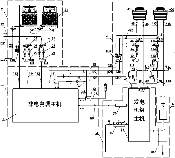
[0022] Such as figure 1 Shown: a complete set of gas-fired cooling, heating and power cogeneration equipment, including generator set main engine 3, generator set integrated transmission and distribution device 4, lithium bromide unit (ie non-electric air conditioner) main engine 11, air conditioning integrated transmission and distribution device 2, controllable System 5.

[0023] In this embodiment, the integrated transmission and distribution device 4 of the generator set has a modular skid-mounted structure, and the integrated air-conditioning transmission and distribution device 2 has a modular skid-mounted structure. The exhaust port of the high-temperature generator of the lithium bromide unit (hereinafter referred to as high-power exhaust The gas port) is integrated with a flue gas heat exchanger 13.

[0024] In this embodime...


PUM


Abstract

A complete fuel gas combined cooling, heating and power device comprises a generator set host, a generator set integrated transmission and distribution device, a lithium bromide unit host, an air conditioner integrated transmission and distribution device and a control system; the generator set integrated transmission and distribution device and the air conditioner integrated transmission and distribution device are both modular skid-mounted structures; the generator set host is provided with an intercooling water outlet port, an intercooling water return port, a cylinder sleeve water outlet port and a cylinder sleeve water return port; the lithium bromide unit host is provided with an air conditioner cooling water outlet port, an air conditioner cooling water return port, an air conditioner cold/warm water outlet port and an air conditioner cold/warm water return port; and a smoke heat exchanger is integrated at a high exhaust opening in the lithium bromide unit host, and a heat exchange water pipeline of the smoke heat exchanger is connected with the lithium bromide unit host. According to the complete fuel gas combined cooling, heating and power device, on the one hand, the structure is compact, the degree of modular integration is high, and the process that users install pipelines and elbows on site can be omitted; and on the other hand, the system running resistance and equipment running energy consumption can be reduced, and time, cost and space are saved.

Description

technical field [0001] The invention relates to the technical field of gas cooling, heating and power generation, in particular to a complete set of gas cooling, heating and power cogeneration device. Background technique [0002] The traditional gas cooling, heating and power transmission and distribution system has the following disadvantages: (1) The structure is scattered and not compact, which not only leads to a large area, but also has a long distance between the systems and long pipelines, which will greatly reduce the system’s operating resistance and equipment’s energy consumption . (2) Due to the scattered structure, it will lead to conservative selection and scattered procurement. Because they are all case designs, the designer cannot determine the quality and performance of the equipment purchased by Party A when designing. All designs are based on theoretical analysis, and it is impossible to test and verify the overall performance of the designed scheme. Ther...

Claims


Application Information

Patent Timeline
IPC IPC(8): F25B25/02F24F5/00F02C6/18F02C7/16
CPCF02C6/18F02C7/16F24F5/0007F25B25/02
Inventor 张跃
Owner BROAD AIR CONDITIONING CO LTD
Why Eureka
Try Eureka