Floor attaching device for house decoration

A technology for fitting devices and floors, which can be used in buildings, building structures, etc., and can solve the problems of narrow floor edges, limited indoor space, and easy fatigue of workers.

Active Publication Date: 2021-06-22
深圳市冠泰装饰集团有限公司
View PDF5 Cites 0 Cited by
  • Summary
  • Abstract
  • Description
  • Claims
  • Application Information

AI Technical Summary

Problems solved by technology

[0003] In the existing floor laying technology, due to the limited indoor space, the floor is usually laid manually, and the floor needs to be moved manually. The floor has a certain weight, and the workers are prone to fatigue, and the edge of the floor is relatively narrow. hurt

Method used


Image

  • Floor attaching device for house decoration
  • Floor attaching device for house decoration
  • Floor attaching device for house decoration

Examples


Embodiment 1

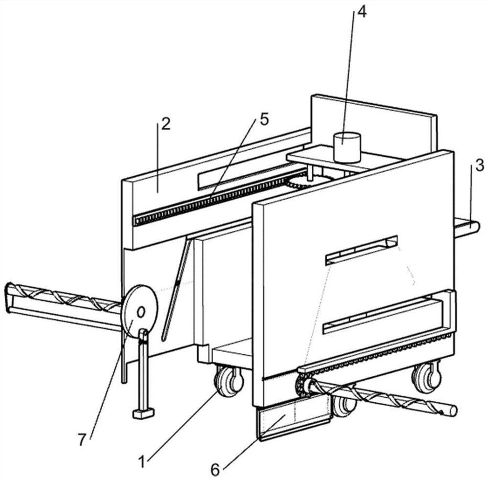
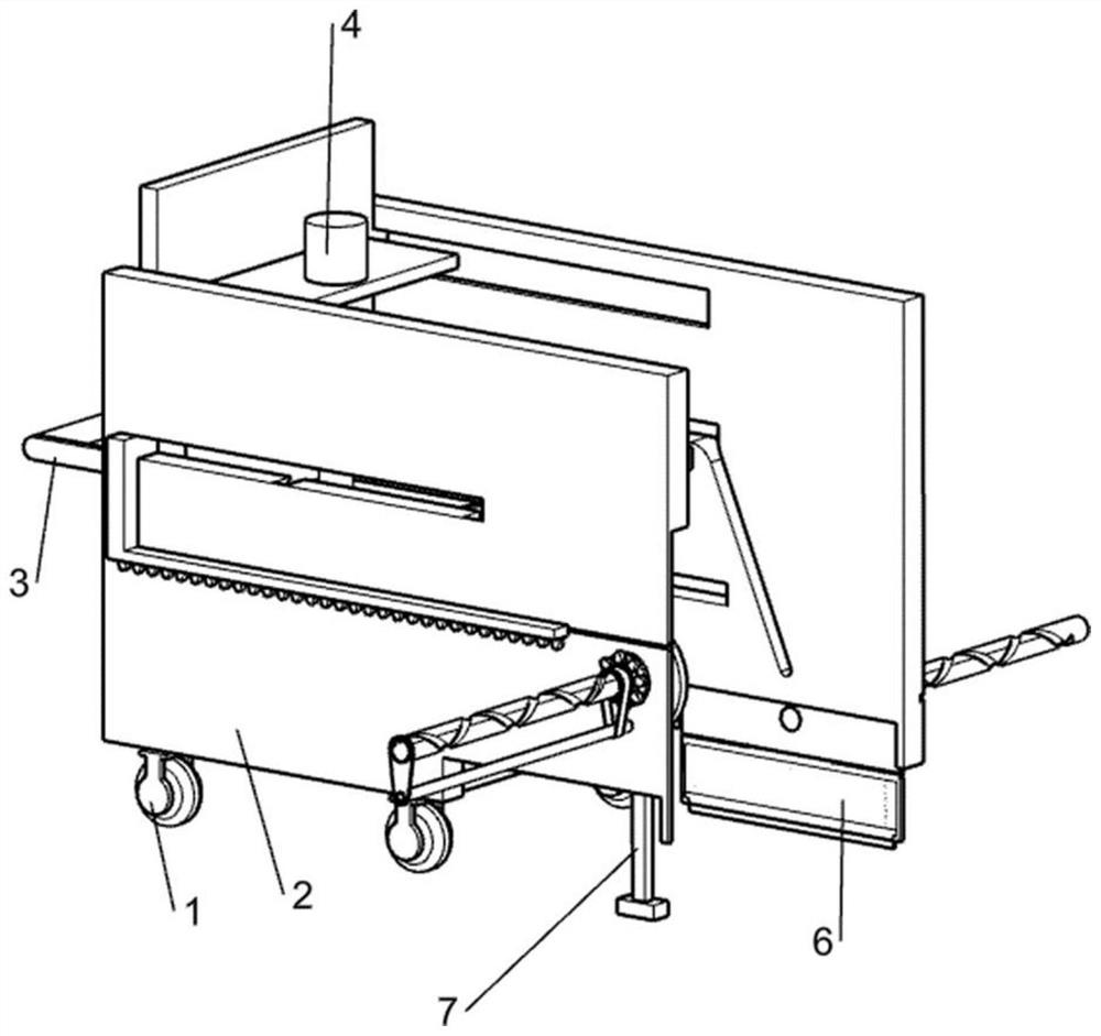
[0024] A floor bonding device for house decoration, such as Figure 1-7 As shown, it includes a universal wheel 1, an outer frame bracket 2, a push rod 3, a lifting mechanism 4, a moving mechanism 5 and a scraping mechanism 6, and the bottom of the outer frame bracket 2 is connected with a universal wheel 1 for distributed rotation, and the outer frame bracket 2 One side is fixed with a push rod 3 for convenient pushing, the lifting mechanism 4 is slidably connected to the outer frame support 2, the moving mechanism 5 is set on the lifting mechanism 4, and the scraping mechanism 6 is rotatably connected to the outer frame support 2 , Scraping mechanism 6 is used for fully smoothing the cement on the ground.

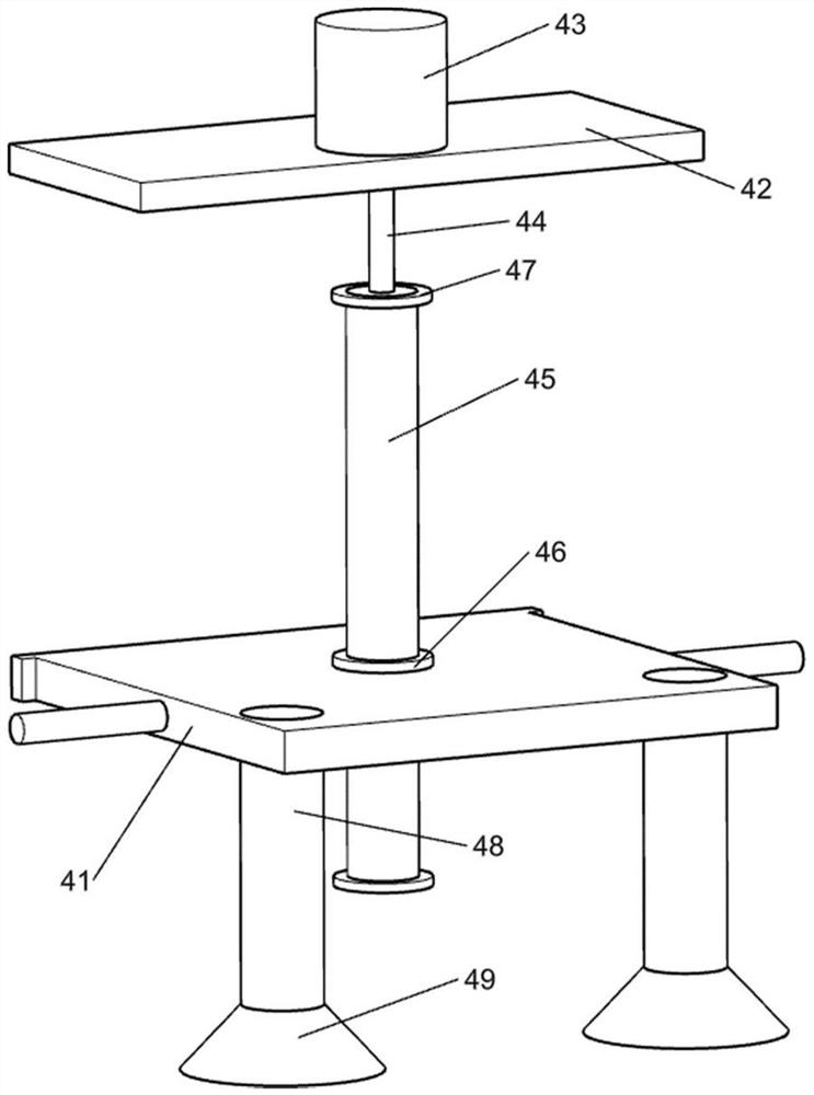
[0025] The lifting mechanism 4 includes a moving plate 411, a slide block 41, a support frame 42, a motor 43, a first power shaft 44, a transmission shaft 45, a sliding sleeve 46, a block 47, a first fixed rod 48 and a suction cup 49, and the moving plate 411 Slidingly c...

Embodiment 2

[0031] On the basis of Example 1, such as Figure 8 As shown, it also includes a fitting and pressing mechanism 7, which is arranged on the outer frame support 2, and the fitting and pressing mechanism 7 is used to make the floor and the ground closely fit, and the fitting and pressing mechanism 7 includes The third rack 71, the second looper 72, the second overrunning clutch 73, the second rotating gear 74, the second reciprocating screw 75, the fixed plate 76, the fixed disc 77, the second power shaft 78, the leather strip 79, the third The fixed rod 710 and the rubber hammer 711 are fixedly connected with the third rack 71 on the moving plate 411 away from the second rack 61, the third rack 71 is connected to the outer frame support 2 in a sliding manner, and the second looper 72 is connected in a rotational manner On the outer frame support 2 away from the first looper 62, the second looper 72 is fixedly connected with a second overrunning clutch 73, and the second overrun...


PUM


Abstract

The invention relates to the field of house decoration, in particular to a floor attaching device for house decoration. The floor attaching device comprises universal wheels, an outer frame support, a push rod, a lifting mechanism, a moving mechanism and the like, wherein the universal wheels are rotatably connected to the bottom of the outer frame support in a distributed mode, the push rod is fixedly connected to one side of the outer frame support, the lifting mechanism is slidably connected to the outer frame support, and the moving mechanism is arranged on the lifting mechanism. According to the device, a first reciprocating screw rod and the device on the first reciprocating screw rod are driven by a slicking mechanism and a first loop to do left-right reciprocating motion, so that a pressing strip does left-right reciprocating motion to flatten cement on the ground, the pressing strip is tightly attached to the cement on the ground under the action of a pressure spring, the cement on the ground is fully flattened, and follow-up floor laying work is facilitated.

Description

technical field [0001] The invention relates to the field of house decoration, in particular to a floor bonding device for house decoration. Background technique [0002] Floor, that is, the surface layer of the ground or floor of a building. Made of wood or other materials, many families use the floor as the main floor material. Floor laying refers to the operation of placing the floor. In order to make the floor clean and tidy, it is necessary to lay a large number of floors on the ground. The classification of floors There are many, according to the structure classification, there are solid wood flooring, laminated wood flooring, three-layer solid wood composite flooring, bamboo wood flooring, anti-corrosion flooring, cork flooring and the most popular multi-layer solid wood composite flooring. [0003] In the existing floor laying technology, due to the limited indoor space, the floor is usually laid manually, and the floor needs to be moved manually. The floor has a ce...

Claims


Application Information

Patent Timeline
Patent Type & Authority Applications(China)
IPC IPC(8): E04F21/22E04F21/20
CPCE04F21/22E04F21/20
Inventor 周锦
Owner 深圳市冠泰装饰集团有限公司
Why Eureka
Try Eureka