
Ring network cable laying device

A technology of cable laying and ring network, which is applied in the direction of cable laying equipment, transportation and packaging, and delivery of filamentous materials, etc., can solve the problems of high work intensity and low efficiency, and achieve the solution of high construction work intensity and low efficiency, and facilitate laying work , The effect of simplifying the operation process

Pending Publication Date: 2022-04-12
CHINA CREC RAILWAY ELECTRIFICATION BUREAU GRP
View PDF0 Cites 0 Cited by
  • Summary
  • Abstract
  • Description
  • Claims
  • Application Information

AI Technical Summary

Problems solved by technology

[0003] Based on this, it is necessary to provide a ring network cable laying device that can improve work efficiency and reduce work intensity in view of the current problem of high construction work intensity and low efficiency of cable laying devices

Method used


Image

  • Ring network cable laying device
  • Ring network cable laying device
  • Ring network cable laying device

Examples


Embodiment Construction

[0035]In order to make the above objects, features and advantages of the present invention more comprehensible, specific implementations of the present invention will be described in detail below in conjunction with the accompanying drawings. In the following description, numerous specific details are set forth in order to provide a thorough understanding of the present invention. However, the present invention can be implemented in many other ways different from those described here, and those skilled in the art can make similar improvements without departing from the connotation of the present invention, so the present invention is not limited by the specific embodiments disclosed below.

[0036] In describing the present invention, it should be understood that the terms "center", "longitudinal", "transverse", "length", "width", "thickness", "upper", "lower", "front", " Back", "Left", "Right", "Vertical", "Horizontal", "Top", "Bottom", "Inner", "Outer", "Clockwise", "Counter...


PUM


Abstract

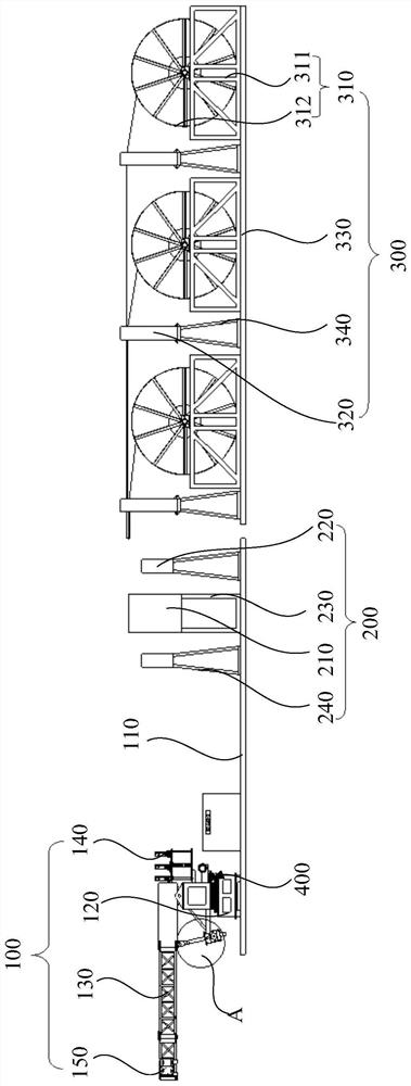
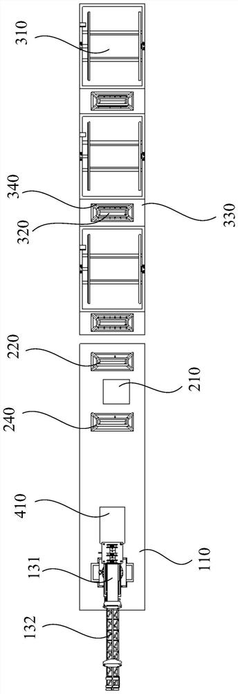
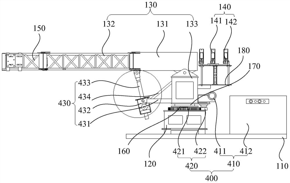
The invention relates to a looped network cable laying device, and the device comprises a pay-off rack structure which comprises at least one coil holder assembly and at least one first guide assembly, and the first guide assembly is disposed at the output end of the coil holder assembly, and is used for guiding a cable outputted by the coil holder assembly; the pay-off arm structure comprises a pay-off assembly, a second guide assembly and a binding belt part, the binding belt part and the second guide assembly are arranged at the two ends of the pay-off assembly respectively, the second guide assembly can convey the cable to the binding belt part through the pay-off assembly, and the cable is bound by the binding belt part; and the cable conveying structure is arranged between the pay-off rack structure and the pay-off arm structure, and the cable conveying structure is used for conveying the cable in the first guide assembly into the second guide assembly. Mechanical construction of cable pay-off is achieved, working efficiency is improved, labor intensity of operators is reduced, and laying work of looped network cables is facilitated.

Description

technical field [0001] The invention relates to the technical field of cable laying equipment, in particular to a ring network cable laying device. Background technique [0002] With the development of society, the use of electricity has become ubiquitous. In life, we often see some ring network cables for power network transmission. The current ring network cable laying device, when carrying out the ring network cable laying operation, first the cable is placed on the cable support, and the ring network cable is output by manpower rotating the reel and the cable installation and arrangement after the wire is unwound. The whole process requires about ten people to complete the laying operation, and this method can only lay one cable at a time, the laying efficiency is low, the construction work intensity is high, and the construction cost is high, which is not conducive to the laying of ring network cables. Contents of the invention [0003] Based on this, it is necessar...

Claims


Application Information

Patent Timeline
IPC IPC(8): H02G1/06B65H49/30B65H57/14
Inventor 潘义红朱艳东康超罗金杜万泉刘小非刘焕斌赵桂旺陈海婷晏春剑刘少伟朱光辉
Owner CHINA CREC RAILWAY ELECTRIFICATION BUREAU GRP
Learn More