Anti-fuse trimming circuit and trimming method thereof

A technology for trimming and adjusting circuits and anti-fuse, which is applied in the direction of logic circuits, electrical components, pulse technology, etc., and can solve the problems of low precision of electrical parameters, poor compatibility, long trimming time, etc.

Pending Publication Date: 2021-07-06
QX MICRO DEVICES
View PDF5 Cites 0 Cited by
  • Summary
  • Abstract
  • Description
  • Claims
  • Application Information

AI Technical Summary

Problems solved by technology

The anti-fuse trimming circuit and its trimming method of the present invention solve the problems of poor compatibility of traditional techniques, low precision of electrical parameters, long trimming time and low efficiency, overcome the shortcomings of traditional techniques, and improve the efficiency of the circuit. Versatility and electrical parameter accuracy, thus improving product quality

Method used


Image

  • Anti-fuse trimming circuit and trimming method thereof
  • Anti-fuse trimming circuit and trimming method thereof
  • Anti-fuse trimming circuit and trimming method thereof

Examples


Embodiment Construction

[0032] The present invention will be described in further detail below in conjunction with accompanying drawing:

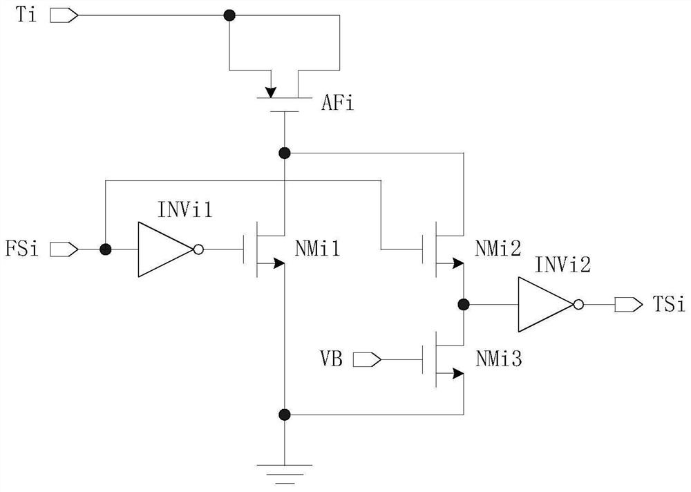
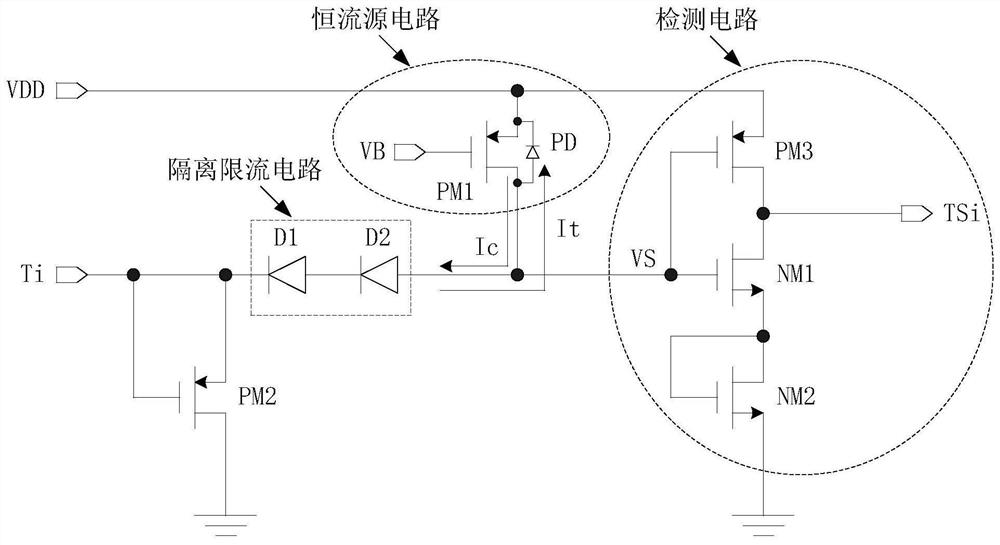
[0033] figure 2 A first embodiment of the invention is shown.

[0034] see figure 1 as shown, figure 2 Shown in is only one of the anti-fuse and its trimming circuit, that is, the i (i=1,2,3,...,n) bit, figure 2 VDD is the power supply voltage, and the bias voltage VB is given to the PMOS field effect transistor PM 1 Provide suitable bias when PM 1 When the drain voltage is low enough, they form a constant current source circuit. The current Ic of the constant current source is designed to be very small, such as 100nA, to reduce power consumption. PD is PM 1 The parasitic body diode; diode D 1 and D 2 It is a P-type general-purpose diode located in different N-wells, which form an isolated current-limiting circuit; the anti-fuse is composed of a PMOS field effect transistor PM 2 constitutes, connected to the trimming input pin T i Between and ground; b...


PUM


Abstract

The invention relates to an anti-fuse trimming circuit and a trimming method thereof. The anti-fuse trimming circuit comprises a constant current source circuit, a detection circuit, an anti-fuse, an isolation current-limiting circuit and a power supply voltage VDD, and the constant current source circuit is sequentially connected with the detection circuit, the isolation current-limiting circuit and the anti-fuse. When the detection circuit detects that the state voltage VS is greater than a certain threshold voltage VTH (VTH is greater than or equal to 1.5 V), a trimming logic signal TSi output by the detection circuit is at a low level; and when the detection circuit detects that the state voltage VS is smaller than the threshold voltage VTH, the trimming logic signal TSi output by the detection circuit is at a high level.

Description

technical field [0001] The invention belongs to the technical field of integrated circuits, and in particular relates to an antifuse trimming circuit in an integrated circuit and a trimming method thereof. Background technique [0002] Antifuse usually refers to a type of device and circuit that can be melted by a certain voltage or current to make it irreversibly change from the original open circuit state to a short circuit state. It is generally used to adjust certain electrical parameters in the circuit, such as: Reference voltage, frequency, etc. [0003] The anti-fuse trimming circuit is a circuit for melting and detecting the anti-fuse. In addition to ensuring reliable and stable melting of the anti-fuse, the anti-fuse trimming circuit must also ensure that the integrated circuit Other devices and circuits in the circuit will not be damaged, and at the same time, it is necessary to detect the open and short-circuit states of the anti-fuse. [0004] figure 1 Shown i...

Claims


Application Information

Patent Timeline
IPC IPC(8): H03K19/094
CPCH03K19/0948
Inventor 毛晓峰黄朝刚李剑
Owner QX MICRO DEVICES
Why Eureka
Try Eureka