
Integrated variable-frequency water supply equipment
A water supply equipment and integrated technology, applied in the field of integrated variable frequency water supply equipment, can solve the problems of inability to realize temperature control of water tank and lack of water flow filtration capability.
- Summary
- Abstract
- Description
- Claims
- Application Information
AI Technical Summary
Problems solved by technology
Method used
Image

Examples
Embodiment Construction
[0029] The present invention is described in detail below in conjunction with accompanying drawing:
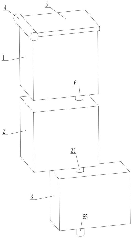
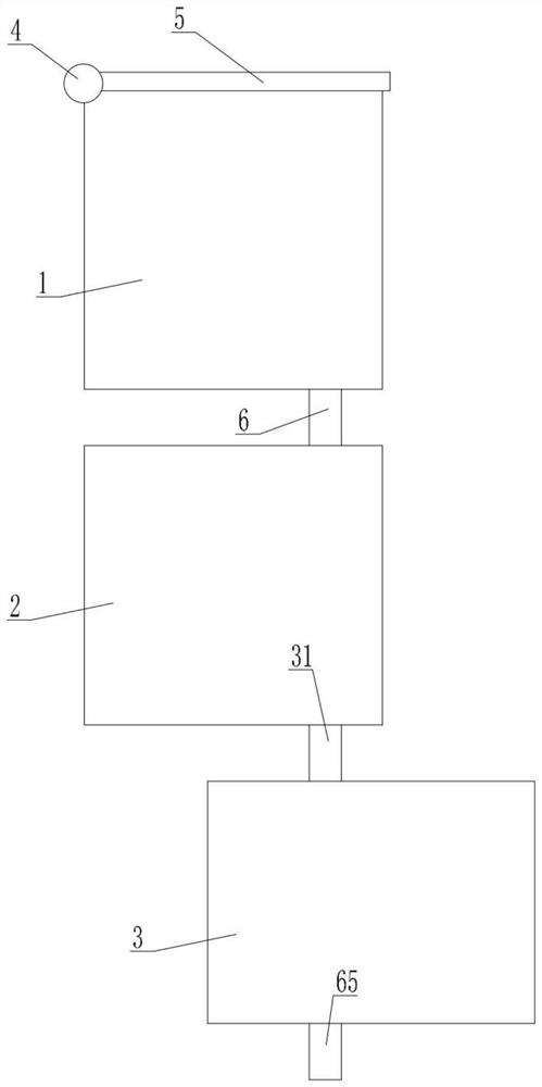
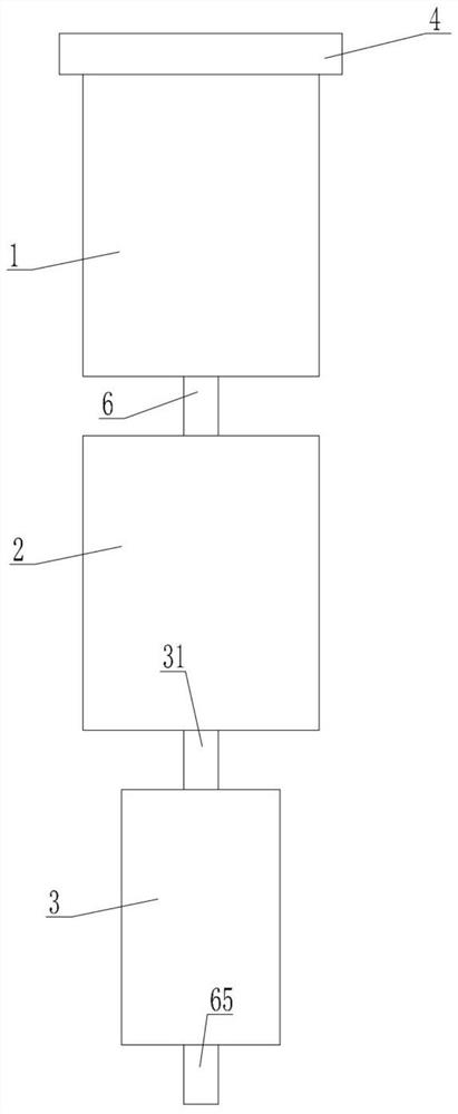
[0030] refer to Figure 1 to Figure 9 , an integrated frequency conversion water supply equipment provided by the present invention includes a filter box 1, a temperature control box 2, and a water supply box 3. The lower side of the filter box 1 communicates with the top of the first flow pipe 6, and the first The bottom end of the circulation pipe 6 extends into the inside of the temperature control box 2, the top left end of the filter box 1 is connected to the left end of the cover plate 5 through the connecting hinge 4, and the lower part of the inner left side of the filter box 1 A motor bottom plate 9 is fixed, a motor 10 is fixed on the top surface of the motor bottom plate 9, an output shaft 11 is provided at the power output end of the top of the motor 10, and the top end of the output shaft 11 extends into the crushing groove 13 Inside, the top end of the output sh...
PUM
 Abstract
Description
Claims
Application Information