Cast-in-place pile concrete vibration device

A vibrating device and concrete technology, which is applied in construction, building structure, construction material processing, etc., can solve problems such as inability to effectively vibrate concrete, floating of steel cages, damage of pile drivers, etc.

Pending Publication Date: 2021-07-30
陈清贵
View PDF1 Cites 0 Cited by
  • Summary
  • Abstract
  • Description
  • Claims
  • Application Information

AI Technical Summary

Problems solved by technology

[0003] Common cast-in-place piles include rotary-dug cast-in-place piles, punch-drilled cast-in-place piles, artificial hole piles, and immersed tube cast-in-place piles. The steel cage is installed in the pile hole, and the concrete is poured into the pile. When the concrete is poured, the concrete segregation, lack of compactness, and poor filling degree are easy to occur. tube) Use a pile driver to push down the pile tip, sink the steel tube and the pile tip into the soil layer, place a steel cage in the steel tube, then pour concrete into the steel tube, and finally pull out the tube to form a pile. The following problems occurred: when the pipe was pulled out, the steel pipe was hung with a steel cage, causing the steel cage to float; the concrete blocked the steel pipe; after the concrete was poured, the concrete was not filled and dense; during the pipe pulling process, the vibration or hammering of the steel pipe caused damage to the steel pipe Scrapped; during the pipe pulling process, the concrete is squeezed by the retractive force of the soil around the steel pipe, resulting in necking
The above-mentioned device pre-solves the problems of blocked pipes, hanging steel cages and uncompacted concrete, but the following problems exist in actual construction: due to the rigid connection between the counterbore steel pipe and the guide pipe, when the vibrator vibrates, it drives the counterbore steel pipe and the guide pipe to vibrate together , because the countersunk steel pipe is in contact with the pile driver and the soil

Method used


Image

  • Cast-in-place pile concrete vibration device
  • Cast-in-place pile concrete vibration device
  • Cast-in-place pile concrete vibration device

Examples


specific Embodiment 1

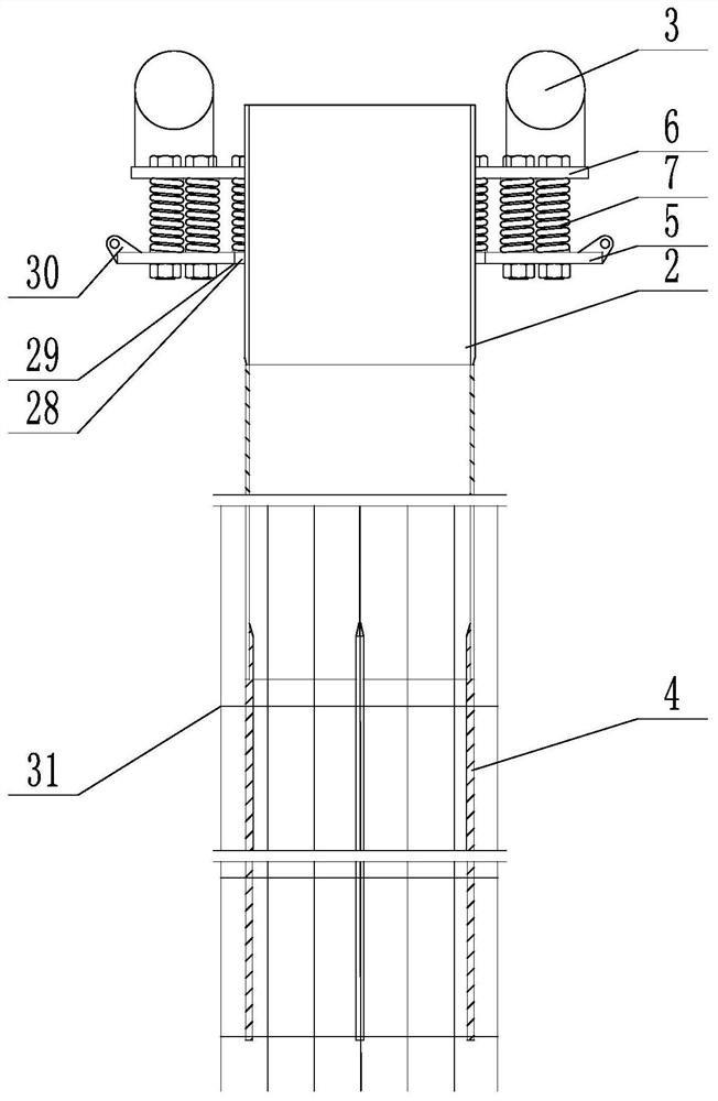
[0027] Such as figure 1 As shown, the present invention relates to a concrete vibrating device for cast-in-situ piles, comprising a base 5, an inner pipe 2, a vibrating device 3, and a steel brazing rod 4. The base 5 is provided with a lifting lug 30, which is used for connecting The steel wire rope is used to lift and fix the base 5. The base 5 can also be located on the ground or on the outer pipe during the construction of the immersed pipe pouring pile. The base 5 is provided with an inner pipe insertion port 29, and the inner pipe 2 Pass through the base 5 from the inner tube insertion port 29, a gap 28 is provided between the outer wall of the inner tube 2 and the inner tube insertion port 29, and a plurality of steel brazing rods 4 are arranged around the inner tube 2 below the tube wall , the steel brazing rod 4 is welded on the inner pipe 2, but it is not limited to welding, it can also be connected by other methods such as screw connection, and the steel brazing rod ...

specific Embodiment 2

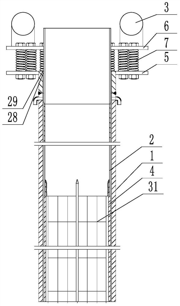
[0029] Such as figure 2 As shown, on the basis of specific embodiment 1, when applied to cast-in-place piles such as immersed pipes, when there are cast-in-situ piles with steel casing wall (outer pipe), lifting lugs 30 may not be provided, and the base 5 is inside The outer pipe 1 extends downward from the pipe insertion opening 29. In this embodiment, the inner pipe insertion opening 29 is circular in shape corresponding to the pile hole, and the outer pipe 1 is inserted into the soil layer above the pile tip using a pile driver.

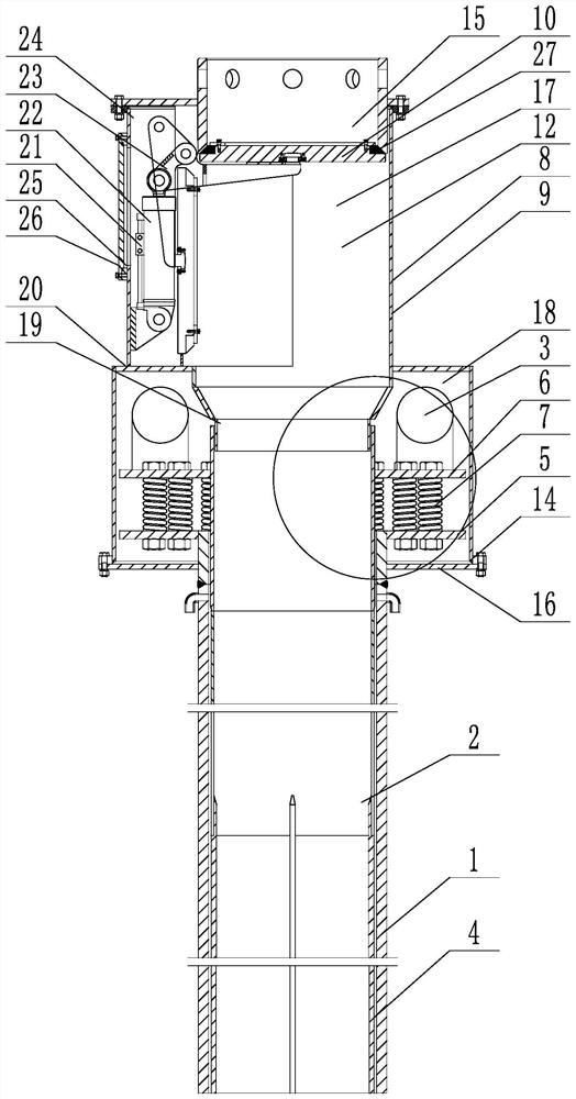
[0030] Further examples such as image 3 , Figure 4 , Figure 5 , Figure 6As shown, it also includes an air pressure sealing device 8, the air pressure sealing device 8 includes a valve body 9, a cover plate 10, a pressurization mechanism 11, a valve cavity 12 is formed in the valve body 9, and an air inlet is opened in the valve cavity 12 13. The valve chamber 12 is connected to the supercharging mechanism 11 through the air inlet 13. The ...


PUM


Abstract

The invention discloses a cast-in-place pile concrete vibration device. The cast-in-place pile concrete vibration device comprises a base, an inner pipe, a vibration device body and steel chisel bars, the base is provided with an inner pipe insertion opening, the inner pipe penetrates through the base from the inner pipe insertion opening, a gap is formed between the outer wall of the inner pipe and the inner pipe insertion opening, the inner pipe is elastically connected with the base, the vibration device body is fixed to the upper end of the inner pipe, and a plurality of steel chisel bars are annularly arranged at the lower end of the inner pipe along the pipe wall and extend downwards. The concrete in the cast-in-place pile is more full and compact, when the cast-in-place pile is applied to the pipe-sinking cast-in-place pile, the steel pipe can be prevented from being hung with a reinforcement cage, the concrete can be prevented from blocking the steel pipe, necking is prevented, and damage to the steel pipe during pipe drawing is reduced.

Description

technical field [0001] The invention relates to the technical field of cast-in-situ piles, in particular to a concrete vibrating device for cast-in-situ piles. Background technique [0002] The pile foundation is a common building foundation, and the pile foundation is used to support the building above, which plays a vital role in the building. Common pile foundations can be divided into prefabricated piles and cast-in-situ piles according to the construction method. The prefabricated piles are prefabricated by the reinforced concrete piles, and then the prefabricated reinforced concrete piles are driven into the ground through the pile machine, while the cast-in-place piles are firstly driven on the construction site. When the predetermined depth is reached, the reinforcement cage is put in and the concrete is poured. [0003] Common cast-in-place piles include rotary-dug cast-in-place piles, punch-drilled cast-in-place piles, artificial hole piles, and immersed tube cast...

Claims


Application Information

Patent Timeline
IPC IPC(8): E04G21/08
CPCE04G21/08
Inventor 陈清贵
Owner 陈清贵
Why Eureka
Try Eureka