Profile steel numerical control feeding and automatic clamping device for profile steel machining production line

An automatic clamping and production line technology, applied to conveyors, conveyor objects, mechanical conveyors, etc., can solve problems such as reducing production efficiency, achieve the effects of improving production efficiency, overcoming technical obstacles, and ensuring accuracy

Pending Publication Date: 2022-04-19
山东山新信息技术有限公司
View PDF0 Cites 2 Cited by
  • Summary
  • Abstract
  • Description
  • Claims
  • Application Information

AI Technical Summary

Problems solved by technology

This process requires manual intervention, which reduces production efficiency. This is a technical obstacle when the equipment is upgraded to an automated production line.

Method used


Image

  • Profile steel numerical control feeding and automatic clamping device for profile steel machining production line
  • Profile steel numerical control feeding and automatic clamping device for profile steel machining production line
  • Profile steel numerical control feeding and automatic clamping device for profile steel machining production line

Examples


Embodiment 1

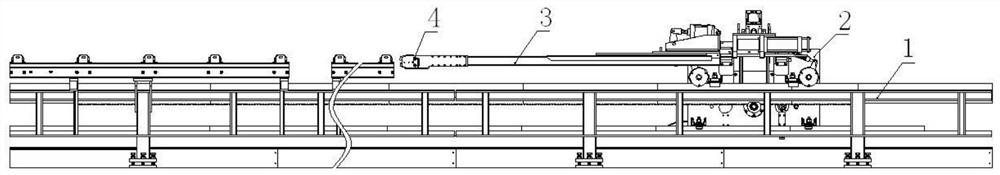
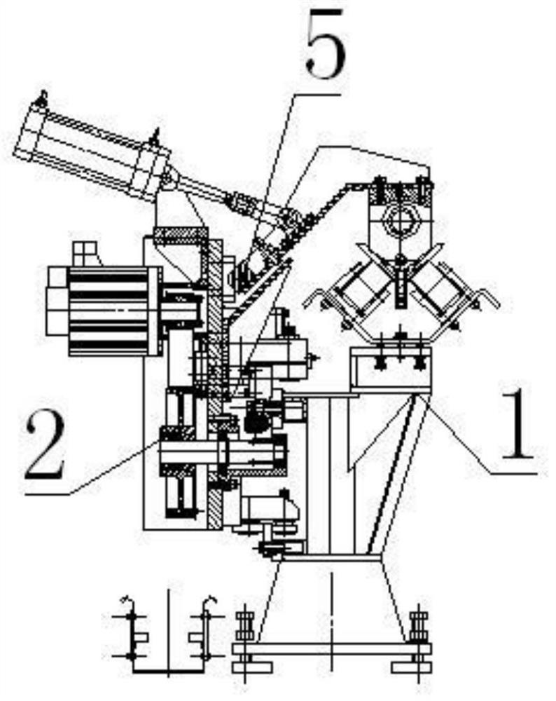
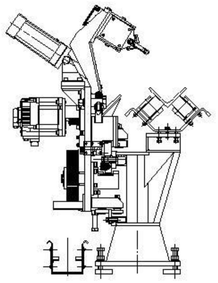
[0041] as attached Figure 4-Figure 21 As shown in the figure, a device for automatic clamping of profiled steel by numerical control feeding in a profiled steel processing production line includes a feeding channel 1 and a CNC feeding trolley 2 installed on the feeding channel 1 and capable of moving along the feeding channel. The feed channel 1 and the numerically controlled feed trolley 2 are all prior art, the feed channel 1 is provided with a rack 14 along its length, the numerically controlled feed trolley 2 is installed on the feed channel 2, and the numerically controlled feed trolley 2 A gear 15 is provided to mesh with the rack 14 provided on the feeding channel 1, and the CNC feeding trolley 2 is driven by its motor 13, and moves along the feeding channel 1 through the meshing transmission of the gear and the rack. Clamp rod 3 and clamp head 4 are arranged on the numerically controlled feed trolley 2, and clamp rod 3 and clamp head 4 are prior art, and clamp head 4 ...

Embodiment 2

[0046] Such as Figure 22-Figure 23 As shown, this embodiment is basically the same as Embodiment 1, the difference is that the signal distinguishing mechanism of the clamp rod in this embodiment is different from that of Embodiment 1. In this embodiment, the mechanism for distinguishing the signal when the clamp rod encounters resistance includes a guide shaft 19 and a compression spring 20 sleeved on the guide shaft 19. One end of the guide shaft 19 is connected to the clamp rod 3, and the other end is connected to the supporting slider. 11, and two inductive switches 18 are arranged on the support slider 11. According to the signal sent by the induction switch, the electronic control system can distinguish the state of the clamp rod being blocked by the difference of spring compression, so as to control the clamp head to clamp the steel. When the clamp head touches the profiled steel, the clamp rod moves backward, driving the guide shaft to move backward and compress the c...


PUM


Abstract

The invention discloses a profile steel numerical control feeding and automatic clamping device for a profile steel machining production line, and belongs to the technical field of profile steel machining production equipment. The numerical control feeding device comprises a feeding channel and a numerical control feeding trolley which is installed on the feeding channel and can move along the feeding channel, a clamp rod and a clamp head are arranged on the numerical control feeding trolley, and the numerical control feeding device is characterized in that a clamp lifting mechanism is arranged on the numerical control feeding trolley, and the clamp rod is horizontally and movably connected with the clamp lifting mechanism through a supporting sliding block mechanism; a clamp rod resistance meeting signal distinguishing mechanism is arranged between the clamp rod and the supporting sliding block mechanism. A profile steel fixing mechanism is arranged on the front portion of the profile steel trough at the tail end of the feeding channel, and a clamp rod guide mechanism is arranged in the profile steel trough at the tail end of the feeding channel. The automatic clamping device can guarantee automatic clamping in the profile steel numerical control feeding process in a profile steel machining production line, full automation of profile steel machining can be achieved, and the production efficiency can be greatly improved.

Description

technical field [0001] The invention relates to a device for automatically clamping profiled steel by numerical control feeding in a profiled steel processing production line, and belongs to the technical field of profiled steel processing. Background technique [0002] At present, in the field of section steel processing, section steel processing equipment is a mature equipment, including section steel feeding, CNC feeding, typing and marking on section steel, punching (drilling) holes, cutting (sawing) and so on. Manual clamping is still required during the CNC feeding and clamping process of section steel, which reduces the efficiency of the equipment and increases the cost of the equipment. [0003] The existing equipment feeds the section steel in the following way: the CNC feeding trolley is installed on the feeding channel and moves along its length direction. The CNC feeding trolley is equipped with a clamp rod, and the clamp on the clamp rod clamps the profile steel...

Claims


Application Information

Patent Timeline
Patent Type & Authority Applications(China)
IPC IPC(8): B65G35/00B65G47/90
CPCB65G35/00B65G47/90
Inventor 陈广先
Owner 山东山新信息技术有限公司
Why Eureka
Try Eureka