Heating body valve

A technology for valves and heaters, which is applied in heating methods, lighting and heating equipment, and valve lifts, and can solve problems such as valve seat travel height restrictions

Inactive Publication Date: 2005-12-14
DANFOSS AS
View PDF0 Cites 0 Cited by
  • Summary
  • Abstract
  • Description
  • Claims
  • Application Information

AI Technical Summary

Problems solved by technology

Similarly, the stroke height of the valve element relative to the valve seat is also limited.

Method used


Image

  • Heating body valve
  • Heating body valve
  • Heating body valve

Examples


Embodiment Construction

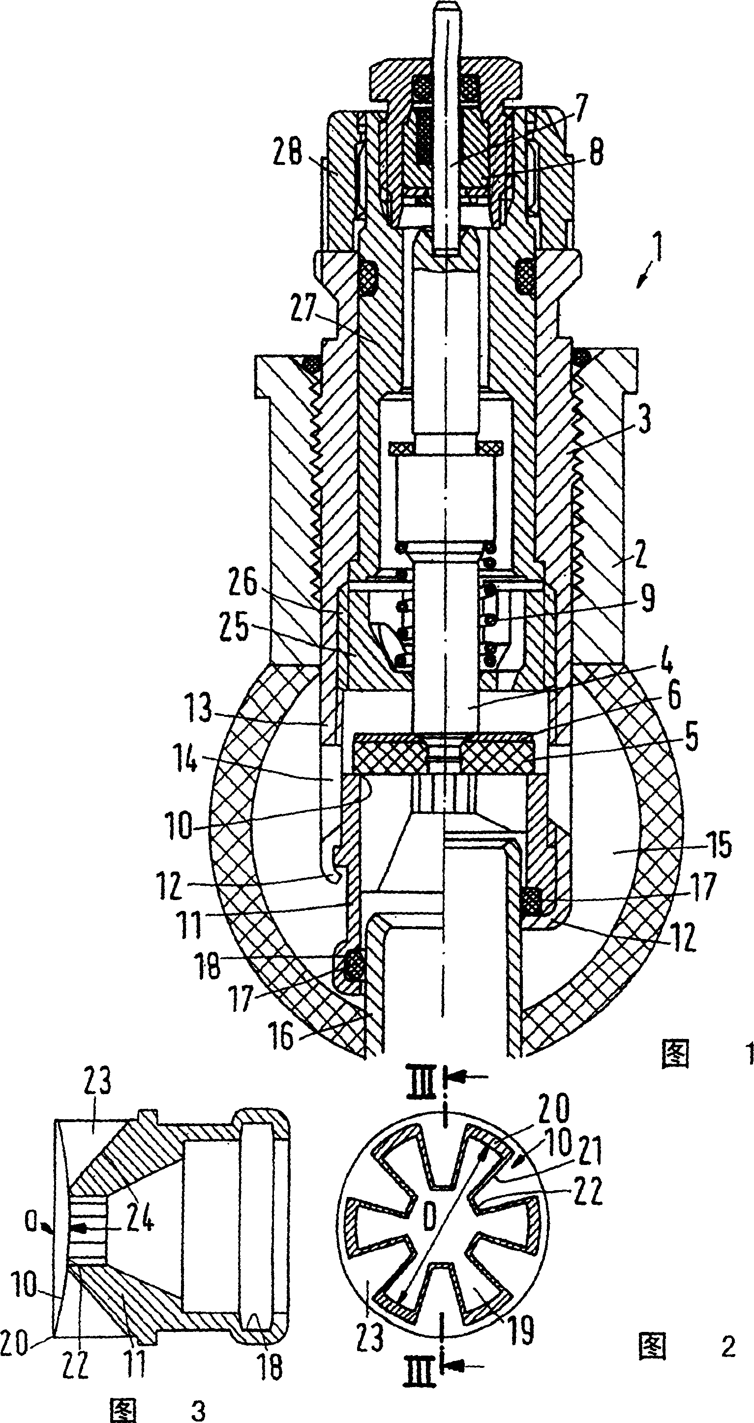
[0025] The heater valve 1 shown in FIG. 1 has a housing 2 into which a valve assembly 3 is screwed. The valve assembly 3 has a valve stem 4 at one end of which a valve member 5 is mounted. The valve element 5 consists of an elastomer material and is supported by a support disc 6 . The valve element 5 is substantially in the shape of a flattened cylinder.

[0026] The valve stem 4 is actuated by an operating pin 7 which is guided by a packing sleeve 8 . The operating pin 7 acts on the valve stem 4 to overcome the force of the opening spring 9 .

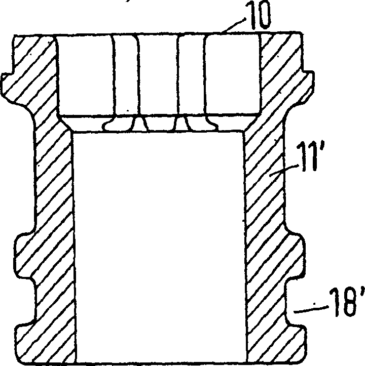
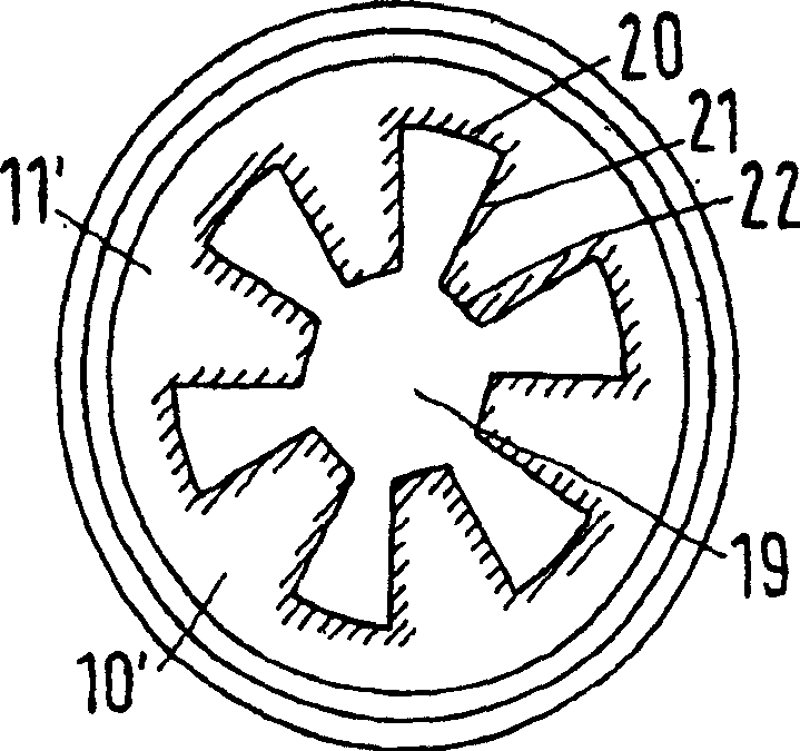
[0027] The valve element 5 interacts with a valve seat 10 on a valve seat element 11 . The valve seat element 11 is shown in two different forms in FIG. 1 . In the left half of FIG. 1, the valve seat element 11 is connected to the valve assembly 3 via a crimp connection 12, wherein the valve assembly 3 has an extension 13, in which a series of holes 14 are again arranged, which allow The heat transfer liquid flows from the valve t...


PUM


Abstract

The invention describes a heating body valve having a valve seat surrounding an orifice (19) which can be closed by a valve element which, in the closed position, follows a closing line (20-22 ) against the valve seat. Larger throughput can be achieved without changing the external dimensions. Wherein the closing line (20-22) has at least one line segment (21), which points inwards in the hole (19), and is also provided with a gap outside along the closing line (20-22) in the closed position of the valve element. Cavity (23).

Description

technical field [0001] The invention relates to a heater valve having a valve seat which surrounds an opening which can be closed by a valve element which rests against the valve seat along a closing line in the closed position. Background technique [0002] Such heater valves are generally known and are used in or on most heaters. The valve element, also called the "valve cone", is pretensioned by a spring in the direction of the bore, ie away from the valve seat. An operating device, usually a thermostat bonnet, that exerts a closing force on the valve element, depending on room temperature, which, if necessary, causes the valve element to rest against the valve seat. Thereby the heating liquid will be stopped and continue to flow in the heating body. The valve element rests on the valve seat along the closure line. The closure line is not a line in the mathematically precise sense, but it is generally a relatively narrow area of ​​contact within which contact occurs be...

Claims


Application Information

Patent Timeline
Patent Type & Authority Patents(China)
IPC IPC(8): F16K1/42F16K47/08
CPCF16K47/08F24D19/1018
Inventor F·加姆
Owner DANFOSS AS
Why Eureka
Try Eureka