Swing seat for automobile machine set

A technology of swing support and unit, applied in the direction of mechanical equipment, power plant, vehicle parts, etc., to achieve the effect of easy replacement

Inactive Publication Date: 2002-11-20
VOLKSWAGEN AG
View PDF0 Cites 20 Cited by
  • Summary
  • Abstract
  • Description
  • Claims
  • Application Information

AI Technical Summary

Problems solved by technology

There is also a problem with the strength of the support arm in the range where it transitions from the straight section to the forked area

Method used


Image

  • Swing seat for automobile machine set
  • Swing seat for automobile machine set
  • Swing seat for automobile machine set

Examples


Embodiment Construction

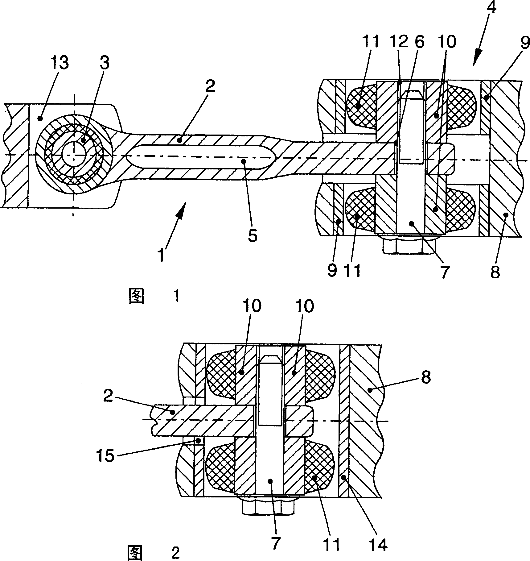
[0021] It is easy to see from FIG. 1 that the oscillating support 1 of the present invention mainly has a support arm 2 , a first bearing 3 and a second bearing 4 .

[0022] The support arm 2 is roughly made into a straight rod shape. In the embodiment shown, there is a gap 5 for weight reduction. The supporting arm 2 can be made such as an aluminum alloy casting or a welded steel structure.

[0023] The bearing 4 is installed in the housing 8 shown in the figure. The oscillating support 1 of the present invention is installed between the units not shown in detail. These units can be, for example, the internal combustion engine and the vehicle body or the subframe of the automobile. At this time, the installation option of the oscillating support can be that the bearing 3 is connected with the engine end, and the bearing 4 is connected with the engine end. The body ends are connected, and vice versa.

[0024] According to the embodiment of FIG. 1 , the bearing 4 has a beari...


PUM


Abstract

The invention relates to a swing support for an automobile unit, which has a support arm (2), a first bearing (3) connected to the unit end of the support arm (12), and a support arm (2) body or vehicle The second bearing (4) connected to the frame end. A vibration damper (11) is arranged between each bearing core (10) of the bearing (3,4) and the bearing outer ring (9,14), wherein the second bearing (4) is made as a split bearing, which It has two bearing cores (10), and at least one bearing outer ring (9, 14).

Description

technical field [0001] The invention relates to a pivot support for a motor vehicle unit according to the preamble of claim 1 . Background technique [0002] To support the engine and transmission unit in an automobile, multiple bearings are generally used. These bearings also prevent or reduce the transmission of vibrations generated when the engine is running to the car body through their spring / damping properties. [0003] Especially in the case of transverse installation of the engine, a similar swing support is often used to reduce the transmission of vibration. Otherwise the occupants of the car will noticeably feel this vibration. [0004] Such pivot supports generally have a support arm with a first bearing connected to the unit end of the support arm and a second bearing enabling it to be supported on the body or subframe. The bearing of the support arm generally has a bearing core and a bearing outer ring, wherein the bearing core is supported on the bearing out...

Claims


Application Information

Patent Timeline
Patent Type & Authority Applications(China)
IPC IPC(8): B60K5/12F16F1/38F16F1/387
CPCB60K5/1241B60G2204/14B60G2204/422B60G2206/11F16F1/3842F16F1/387
Inventor C·舒尔策R·施密德特
Owner VOLKSWAGEN AG
Why Eureka
Try Eureka