Automatic alligning method for optical waveguide device and optical fibre array

An optical fiber array and automatic alignment technology, which is applied to the coupling of optical waveguides, instruments, non-electric variable control, etc., can solve difficult and time-consuming problems

Inactive Publication Date: 2002-12-04
GUANGXUN SCI & TECH WUHAN
View PDF1 Cites 26 Cited by
  • Summary
  • Abstract
  • Description
  • Claims
  • Application Information

AI Technical Summary

Problems solved by technology

It can be seen from the figure that the waveguides in the waveguide device (output end) are on the same plane, and the distance between them is D microns. The size of the waveguide itself is generally only a few microns, and the optical fibers at the output end of the fiber array are also on the same plane. The distance between

Method used


Image

  • Automatic alligning method for optical waveguide device and optical fibre array
  • Automatic alligning method for optical waveguide device and optical fibre array
  • Automatic alligning method for optical waveguide device and optical fibre array

Examples


Embodiment Construction

[0021] Figure 7 shows a schematic diagram of the system for automatic alignment of waveguide devices and fiber arrays, mainly including electric fine-tuning racks, light sources and optical power meters.

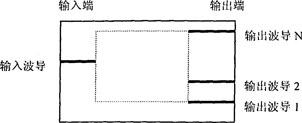
[0022] The automatic alignment between the waveguide device and the fiber array will be described below by taking an M×N channel waveguide device as an example (M and N are arbitrary integers). Generally speaking, the alignment of the input fiber array and the waveguide device is relatively easy. Although the input end of the waveguide device has M channel waveguides, it only needs to align one fiber in the input fiber array with a certain waveguide at the input end of the waveguide device. Can. If all M channels are required to be aligned at the input end of the waveguide device, it is only necessary to properly rotate the input fiber array along the Z axis shown in the coordinate system in FIG. 7 . When M×N channels are aligned, the first is horizontal adjustment and coar...


PUM


Abstract

The invention relates to the method for automatically aligning the optical wave guide part with the optical fiber array, including the coarse alignment, fine alignment and the equalization of energy in each channel. The mixed type algorithm for automatic alignment is adopted in the fine alignment. The procedure of the fine alignment is as follows: With relatively great scanning range and step size, using the numerical value plot mode alignment algorithm searches the position of the relative maximum value of energy in K channel further. With relatively small scanning range and step size, usingthe numerical value plot mode alignment algorithm searches the position of the final absolute maximum value of energy in K channel. Using the fast aligning method-the rotation method searches the maximum value of energy in J channel.

Description

technical field [0001] The invention relates to a method for automatic alignment of an optical waveguide device and an optical fiber array, which is used in the coupling packaging of the optical waveguide device, and each light guiding channel (ie waveguide) on the waveguide device and the optical fiber in the optical fiber array are one by one Alignment method. Background technique [0002] Planar optical waveguide devices are rapidly entering the optical communication market, but their difficult packaging work has become a bottleneck limiting their development. The packaging of planar optical waveguide devices involves the six-dimensional precision alignment of fiber arrays and waveguide devices, which is difficult. At present, device manufacturers at home and abroad generally adopt the method of manual coupling and packaging. Manually coupled waveguide devices have disadvantages such as slow speed, poor alignment accuracy, poor repeatability, many human factors, and inca...

Claims


Application Information

Patent Timeline
IPC IPC(8): G02B6/26G05D3/00
Inventor 马卫东杨涛许远忠
Owner GUANGXUN SCI & TECH WUHAN
Why Eureka
Try Eureka