Computer power supply

A power supply device, computer technology, applied in the direction of circuit devices, battery circuit devices, measuring devices, etc.

Inactive Publication Date: 2004-05-26
NIPRON
View PDF1 Cites 6 Cited by
  • Summary
  • Abstract
  • Description
  • Claims
  • Application Information

AI Technical Summary

Problems solved by technology

[0005] In the above-mentioned patent documents, by reducing the flow rate of the cooling fan when the load current is small, compared with the case of driving multiple cooling fans at all, the efficiency can be improved somewhat, but the problem has not been fundamentally solved.

Method used


Image

  • Computer power supply
  • Computer power supply
  • Computer power supply

Examples


Embodiment Construction

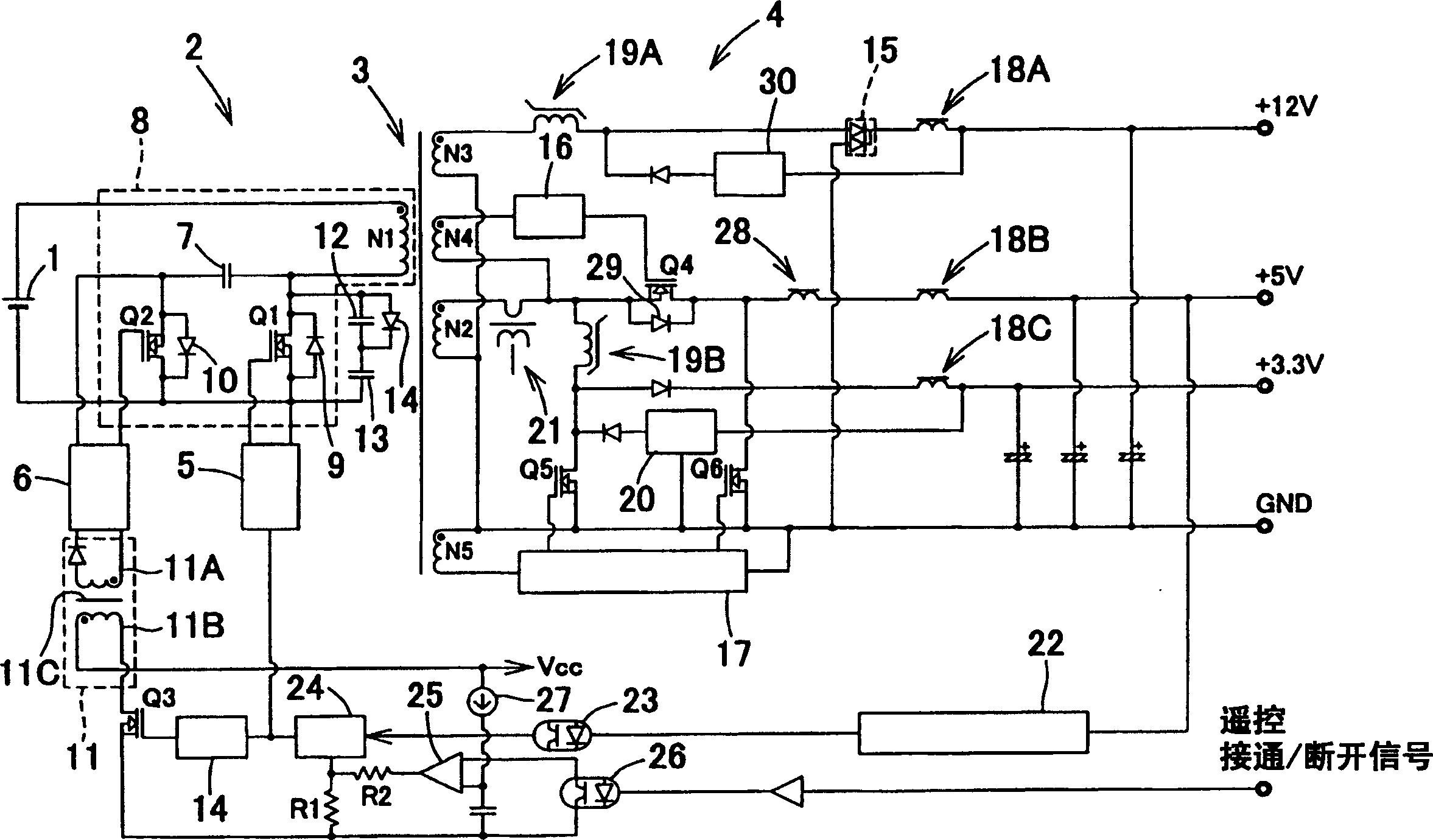
[0026] figure 1 It shows a power supply device for a computer, and generally, for example, a circuit for rectifying and converting the AC from a commercial AC power supply to a DC voltage is provided, and the DC voltage from this circuit is used. For the sake of simplicity of description, in figure 1 An example including a battery 1 generating a DC voltage is shown, but it is not limited to the example, figure 1 The secondary side output shown should be able to output three output voltages of +12, +5V, and +3.3V, but it does not matter how to set the number of outputs and the output voltage.

[0027] The aforementioned power supply device for a computer is composed of a primary side switching circuit 2 that operates with the DC voltage of the battery 1 as an input, and various devices for driving a computer by using the output from the switching circuit 2 via a high frequency transformer 3. The secondary side output circuit 4 provided on the secondary side of 3 constitutes. ...


PUM


Abstract

An object of the present invention is to provide a computer power supply in which, by improving the circuit itself, internal heat loss can be reduced, thereby greatly improving efficiency. A partial resonance circuit 8 is constituted by a primary side winding N1 of a high frequency transformer 3, a resonance condenser 7 , and two switching elements Q1, Q2, a secondary side output circuit 4 for driving a load is connected to a secondary side of the high frequency transformer 3 via a winding, and a reverse converter for driving and halting the first switching element and second switching element by causing the respective phases thereof to differ on the basis of a driving signal is provided.

Description

technical field [0001] The present invention relates to a device for driving various loads by using a DC output rectified by an AC-side power supply circuit, for example, from a commercial AC power supply (AC), or a DC voltage from a DC power source such as a battery or storage battery. Computer power supply unit. Background technique [0002] When providing a switching power supply with a high output capacity (200 to 300W) for the size of, for example, 1U (44mm in height) as the above-mentioned computer power supply unit, in order to output an output capacity of 210W or more in a small size, the conventional method uses multiple Cooling fans are used to avoid the reduction in efficiency caused by internal heat consumption. Not only the efficiency is only 65% ​​to 68% at best, but also because the more cooling fans there are, the greater the power consumption, so it is not possible to improve the efficiency. It is urgently expected Improve soon. [0003] A configuration ha...

Claims


Application Information

Patent Timeline
Patent Type & Authority Applications(China)
IPC IPC(8): H02M3/28H02M3/335
CPCH02M3/33576H02M3/33561H02M2001/0048Y02B70/1491H02M1/0048Y02B70/10
Inventor 山田富治辰巳章
Owner NIPRON
Why Eureka
Try Eureka