
Adiabatic bend transitions for multimode fibers

a multi-mode fiber and adiabatic bend technology, applied in the field of fiber optic applications, can solve the problems of limiting the power scaling of fiber amplifiers to higher power levels, reducing the efficiency of high-power fiber amplifiers, and reducing the effective fiber core area to a certain level, so as to reduce modal coupling, improve output beam quality, and reduce the effect of modal coupling

Active Publication Date: 2013-07-16
KONGSBERG DISCOVERY AS
View PDF7 Cites 0 Cited by
  • Summary
  • Abstract
  • Description
  • Claims
  • Application Information

AI Technical Summary

Benefits of technology

This approach enhances the efficiency of high-power fiber amplifiers by reducing modal coupling and maintaining high beam quality, as measured by the M2 factor, and allows for the efficient coupling of higher-order modes back into the fundamental mode, improving the output beam quality.

Problems solved by technology

However, nonlinear effects (namely stimulated Brillouin scattering, stimulated Raman scattering, and / or self-phase modulation) limit the power scaling of fiber amplifiers to higher power levels.
This limits the effective fiber core area to a certain level.
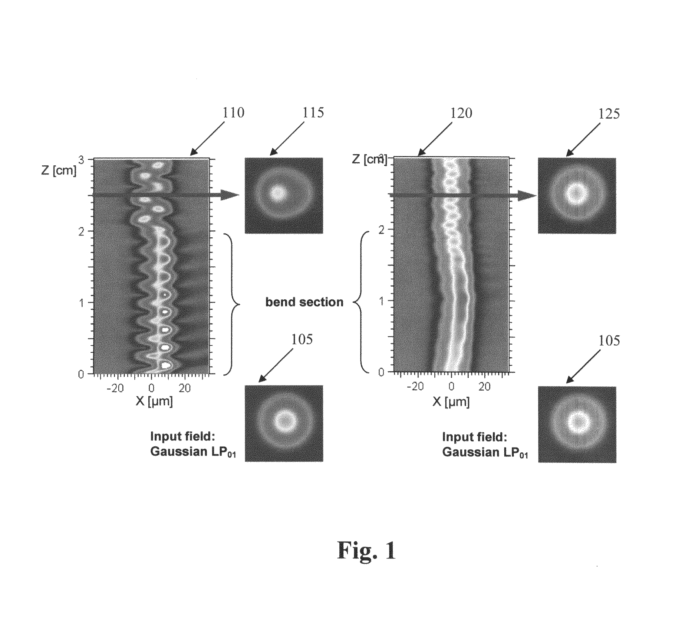
Fiber bends not only induce pure bend loss to the modes, but also inflict a transition loss at the transition from a straight fiber to a bend section and vice versa.
The transition loss as such is highly underestimated by most people regarding LMA fibers, and has a huge impact on the performance when trying to reach smaller bend radii.
The shortcoming of these considerations lies in seeing the transition loss as a simple power loss while neglecting mode coupling, which is inadequate for devices where the mode distribution is important.
Little research has been performed on bend-induced mode coupling and very little, if any, research has involved the investigation of bend induced mode coupling for adiabatic bends in LMA fibers.
Imperfection in real fiber amplifiers, e.g., due to fiber splicing, provokes the generation of higher order modes, thereby decreasing the mode quality at an early stage.
On top of that, a tight bending at the beginning induces a significant loss to the fundamental mode as well, which makes a reduction of the bend radius inevitable.
It is believed that no other preliminary work has been done to design an optimized adiabatic fiber bend transducer.

Method used


Image

  • Adiabatic bend transitions for multimode fibers
  • Adiabatic bend transitions for multimode fibers
  • Adiabatic bend transitions for multimode fibers

Examples


Embodiment Construction

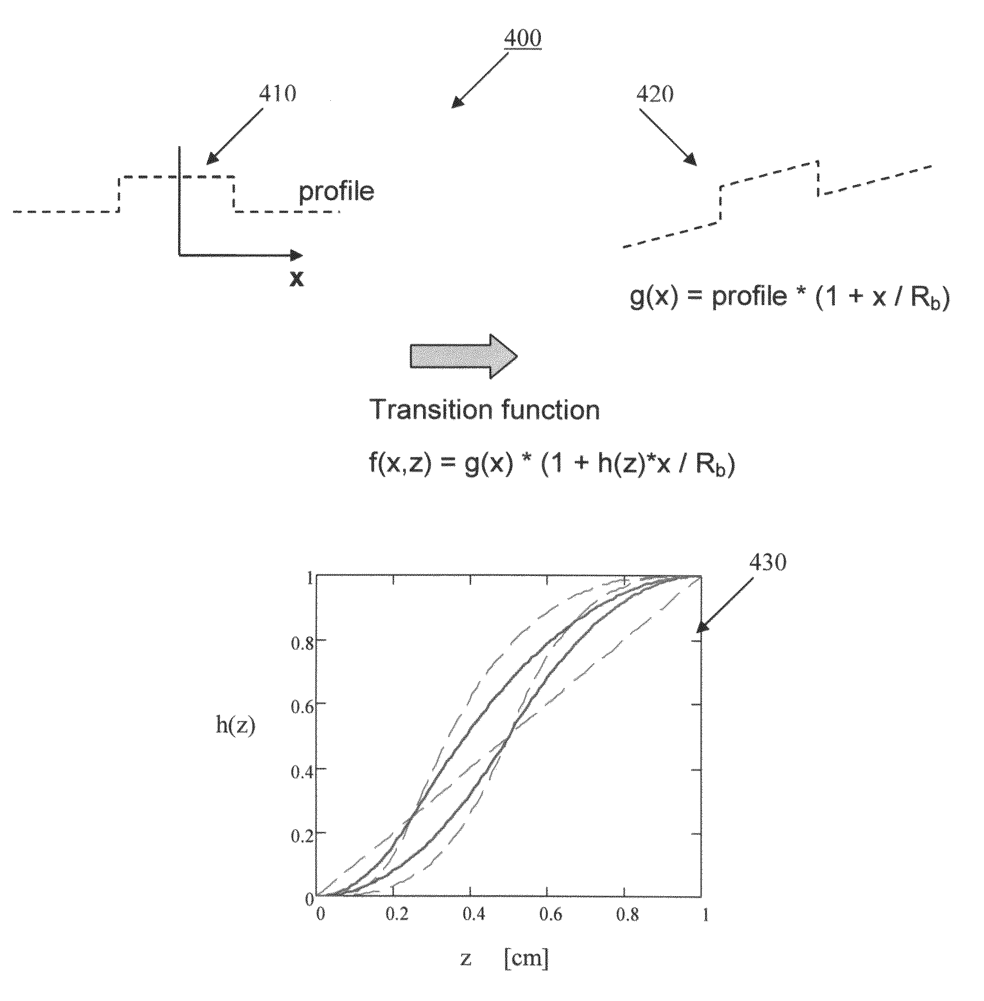
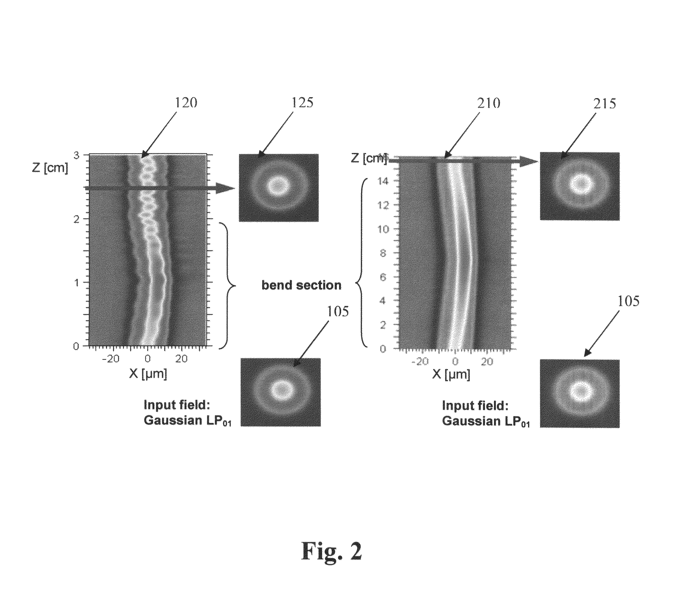
[0033]Further features and advantages of the invention, as well as the structure and operation of various embodiments of the invention, are described in detail below with reference to the accompanying FIGS. 1-12, wherein like reference numerals refer to like elements. The present invention implements guided adiabatic fiber bend transitions to support higher-order mode filtering and / or fundamental mode amplification for passive and active fiber assemblies such as, but not limited to step-index LMA fibers and photonic crystal fibers (also called holey fibers, hole-assisted fibers, microstructure fibers, or microstructured fibers). The fibers themselves may be passive or doped, normal or polarization maintaining, and incorporated into fiber assemblies or amplifiers, which are run in continuous wave or pulsed operation. The invention can be applied to virtually any fiber that guides multiple modes, for which the modal distribution changes by bending the fiber.

[0034]In an embodiment of t...


PUM


Abstract

Guided adiabatic bend transitions for multimode fibers are presented to preserve the power of guided light in the fundamental mode while guiding from one level of curvature to another for improved operation of mode filters and fiber amplifiers. A method is provided to find the guidance path. Implementations of these transducers include modal power back converters, and guidance paths into and out of higher order mode filtering devices which work on bending. A spiral structure is shown to incorporate adiabatic bends for a forward-pumped fiber amplifier.

Description

BACKGROUND OF THE INVENTION[0001]1. Field of Invention[0002]This invention relates to fiber optic applications and more specifically, to an adiabatic bend transducer to support higher-order mode filtering and / or fundamental mode amplification for passive and active fiber assemblies.[0003]2. Description of Related Art[0004]Rare-earth doped fiber amplifiers offer important advantages compared to solid-state lasers in terms of power conversion, transverse mode stability, compactness and thermal management. See, e.g., A. Tünnerman et al., “The renaissance and bright future of fibre lasers,” J. Phys. B 38, pp. 681-693 (2005), the disclosure of which is incorporated by reference herein in its entirety. A double cladding architecture and enlarged fiber cores allow the amplification of optical signals up to power levels appropriate for laser processing such as micro-machining and laser marking. See E. Snitzer et al., “Double-clad, offset core Nd fiber laser,” Optical Fiber Sensors, OSA Tech...

Claims


Application Information

Patent Timeline
Patent Type & Authority Patents(United States)
IPC IPC(8): G02B6/036G02B6/24
CPCG02B6/14G02B6/3628H01S3/06704H01S3/06754H01S3/0804H01S3/102H01S3/1067H01S3/1618
Inventor GRUNSTEIDL, STEFAN FRANZSOUSA, JOAO M.BERENDT, MARTIN O.MUNIZ, ROSA M.GUERREIRO, PAULO T.
Owner KONGSBERG DISCOVERY AS
Learn More