Liquid crystal display device

A liquid crystal display device and liquid crystal layer technology, applied in optics, instruments, nonlinear optics, etc., can solve the problems of narrow application range and poor image display quality, and achieve the effects of wide application fields, not easy to scratch, and eliminate damage

Inactive Publication Date: 2005-07-20
HONG FU JIN PRECISION IND (SHENZHEN) CO LTD +1
View PDF0 Cites 16 Cited by
  • Summary
  • Abstract
  • Description
  • Claims
  • Application Information

AI Technical Summary

Problems solved by technology

[0008] In order to solve the defects of poor image display quality and narrow application range of the prior art liquid crystal display device, the present invention provides a liquid crystal display device with better image display quality and wide application range

Method used


Image

  • Liquid crystal display device
  • Liquid crystal display device
  • Liquid crystal display device

Examples


Embodiment Construction

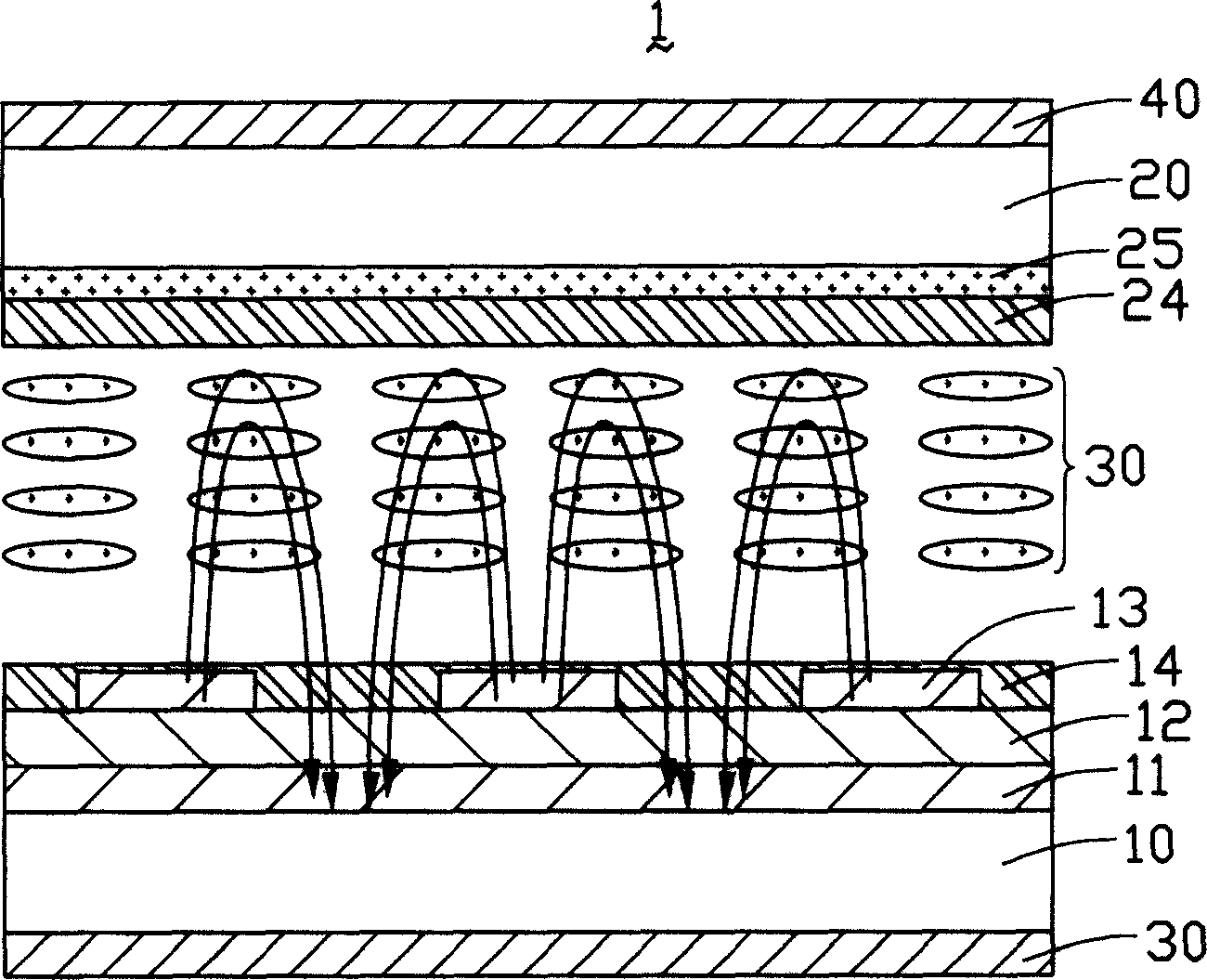
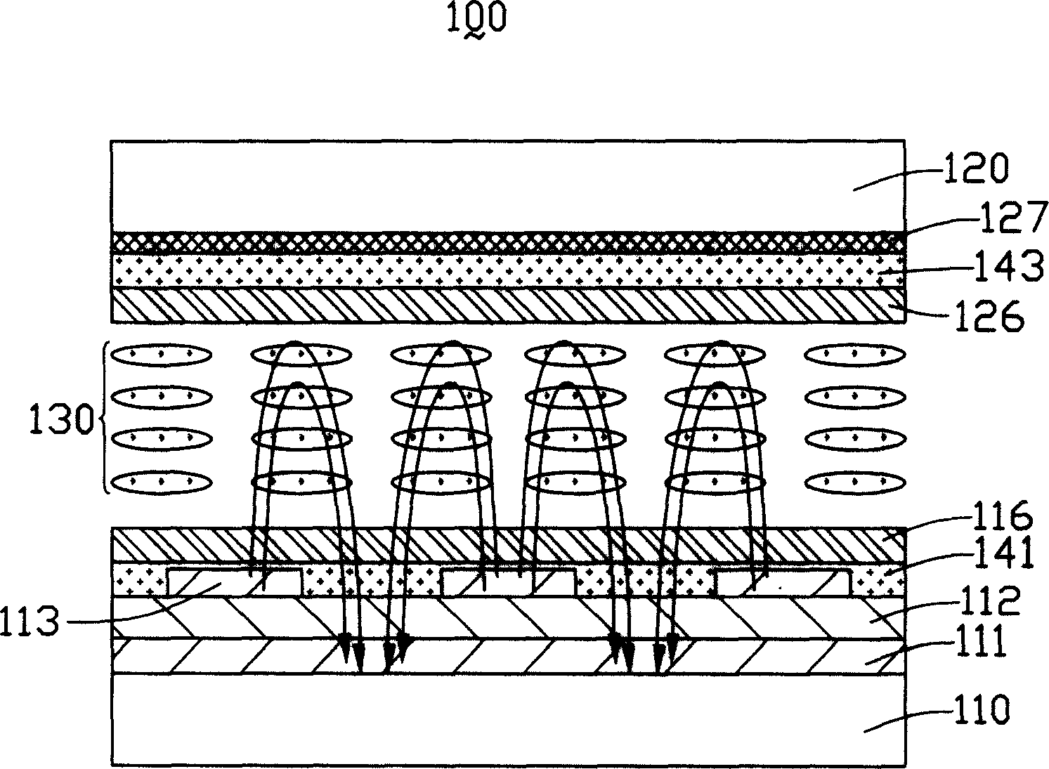
[0017] figure 2 It is a schematic cross-sectional view of the first embodiment of the liquid crystal display device of the present invention. Taking the transmissive FFS type liquid crystal display device as an example, the liquid crystal display device of the present invention includes a lower substrate 110, an upper substrate 120 arranged opposite to the lower substrate 110, an upper substrate 120, an The liquid crystal layer 130 is located between the two substrates 110 and 120 .

[0018] A common electrode 111 , an insulating layer 112 , a pixel electrode 113 , a lower polarizer 141 and a lower alignment layer 116 are sequentially disposed on the inner surface of the lower substrate 110 . A color filter 127 , an upper polarizer 143 and an upper alignment layer 126 are sequentially disposed on the inner surface of the upper substrate 120 . Wherein, the liquid crystal layer 130 includes a plurality of liquid crystal molecules, and the insulating layer 112 is made of a tran...


PUM

PropertyMeasurementUnit
thermal resistanceaaaaaaaaaa

Abstract

This invention provides a kind of liquid crystal display device including a first basal board, a second basal board, a liquid crystal layer and two pieces of light-polarizing slices. The liquid crystal layer is located between the first and the second basal board. The two light-polarizing slices are respectively equipped on the first and the second basal board. Thereinto at least one light-polarizing slice is equipped at the inside of the corresponding basal board.

Description

【Technical field】 [0001] The invention relates to a liquid crystal display device. 【Background technique】 [0002] Liquid crystal display devices are widely used due to their characteristics of low radiation, light and thin size, and low power consumption. With the maturity and innovation of related technologies, there are more and more types of liquid crystal display devices. [0003] In terms of the utilization of incident light, liquid crystal display devices can be classified into three types: transmissive, semi-transmissive and semi-reflective, and reflective. However, whether it is a transmissive, transflective or reflective liquid crystal display device, usually when the user views the display screen of the liquid crystal display device from different angles, the contrast of the image will decrease as the viewing angle increases. This results in viewing angle limitations. In order to overcome the defects of narrow viewing angles in early Twisted Nematic (TN) and Sup...

Claims


Application Information

Patent Timeline
Patent Type & Authority Applications(China)
IPC IPC(8): G02B5/30G02F1/1335G02F1/136
Inventor 杨秋莲彭家鹏
Owner HONG FU JIN PRECISION IND (SHENZHEN) CO LTD
Why Eureka
Try Eureka