Display Apparatus

a technology of display apparatus and display screen, which is applied in the direction of cathode-ray tube indicators, static indicating devices, instruments, etc., can solve the problems of reducing color saturation, increasing circuit size, and increasing the cost of the circuit, so as to prevent the reduction of the color saturation of each reproduced color, improve the display quality, and improve the luminance

Inactive Publication Date: 2009-01-01
SHARP KK
View PDF9 Cites 29 Cited by
  • Summary
  • Abstract
  • Description
  • Claims
  • Application Information

AI Technical Summary

Benefits of technology

[0015]According to the arrangement, a minimum luminance value is assumed to be a W (white) color signal for a W (white) picture element. The luminance extended and converted color signals are outputted for an R (red) picture element, a G (green) picture element, and a B (blue) picture element. Each of the luminance extended and converted color signals is obtained by subtracting, from each of the luminance extended color signals, a corrected minimum luminance value obtained by multiplying the minimum luminance value by a coefficient k. Accordingly, four color signals including the W (white) color signal and the luminance extended and converted color signals are generated from three color signals and outputted. This allows to improve the luminance by adding the W (white) signal and at the same time prevent reduction in color saturation of each reproduced color which reduction is caused by the luminance extended and converted color signals. As a result, display quality can be improved.
[0016]Moreover, according to the arrangement, each of the three color signals before subjected to luminance extension is subjected to luminance compression in accordance with a luminance of a preceding frame. Therefore, by varying a compression ratio in accordance with a scene corresponding to a preceding frame in image display, it becomes possible to perform optimum luminance extension in accordance with a scene of an image. This allows luminances of primitive colors to be extended to a certain extent. This provides an advantage that reduction in color saturation of a primitive color can be suppressed to minimum even in a case where the primitive color comes adjacent to white color. As a result, display quality can be improved.
[0017]Furthermore, in the arrangement, the coefficient k is set so that the luminance of the W (white) color becomes equal to or less than a minimum luminance of the luminance extended and converted signals of the three colors. The coefficient k is used to obtain a corrected minimum luminance value by multiplying the minimum luminance value by the coefficient k. This allows to prevent the occurrence of a white spot particularly during gray display and to improve display quality.

Problems solved by technology

However, this RGBW color liquid crystal display tends to cause reduced color saturation.
However, the more the size of the W pixel is reduced so that the size becomes smaller than the respective sizes of the RGB pixels, the more an effect of improvement in luminance is damaged.
This gives rise to an increase in a circuit size, and in cost of the circuit.
Accordingly, with this method, luminance is not improved, and, moreover, the occurrence of reduced color saturation becomes significant.
However, this does not lead to improvement of luminance, because luminance of an input signal is not extended.
However, the conventional invention disclosed in Patent Document 3 has a problem that displayed image quality deteriorates.
This results in the problem of deterioration in image display quality.
This causes a pattern where an image looks unnatural, thereby presenting the problem of deterioration in display image quality.

Method used


Image

  • Display Apparatus
  • Display Apparatus
  • Display Apparatus

Examples


Embodiment Construction

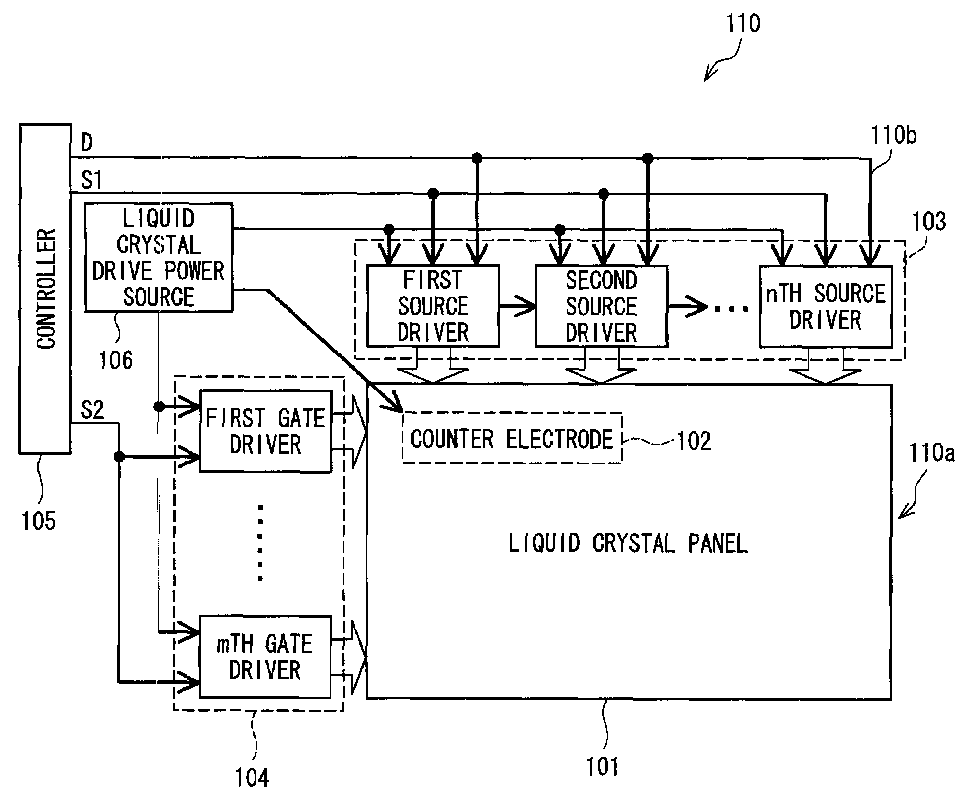
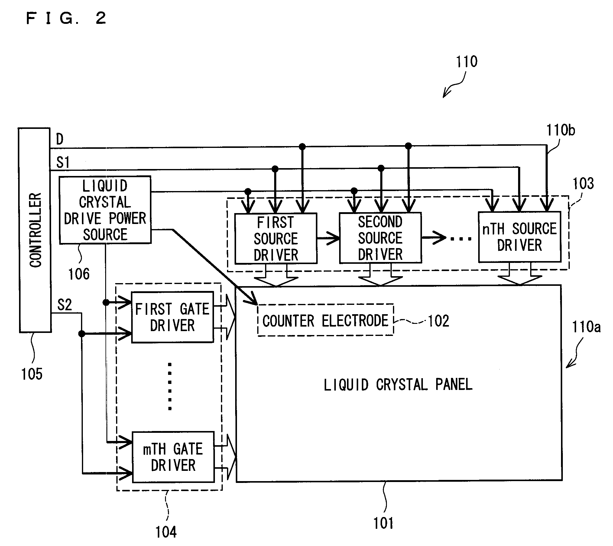
[0026]One embodiment of a liquid crystal display according to a display apparatus of the present invention is explained below, with reference to FIGS. 1 through 8. An active matrix system using TFTs (Thin Film Transistors) as switching elements is known as a system capable of performing a display of high definition, among various display types of a liquid crystal display apparatus. As illustrated in FIG. 2, a liquid crystal display apparatus 110 employing the active matrix system includes a liquid crystal display section (display section) 110a and a liquid crystal drive circuit (drive signal outputting section) 110b serving as a liquid crystal driving device that drives the liquid crystal display section 110a.

[0027]The liquid crystal display section 110a includes a TFT-type liquid crystal panel 101. The liquid crystal panel 101 has pixels (dots) arranged in a matrix (lattice). In the present embodiment, for example, pixels are arranged in a matrix of 1024×768 pixels (XGA (eXtended ...


PUM


Abstract

A display apparatus includes a luminance compressing section, a luminance extending section, and a W calculating section. The luminance compressing section subjects three color signals to luminance compression according to a luminance in a preceding frame, and outputs compressed color signals. The luminance extending section outputs luminance extended and converted color signals of respective three colors. Each of the luminance extended and converted color signals is obtained by subtracting a corrected minimum luminance value from a luminance extended color signal which is obtained by subjecting the compressed color signal to luminance extension at a luminance extending rate S in accordance with a function F(t). The function F(t) has as a variable a ratio t of a minimum luminance value to a maximum luminance value of the compressed color signals. The corrected minimum luminance value is obtained by multiplying the minimum luminance value by a coefficient k. The W calculating section outputs the minimum luminance value as a white signal. The function F(t) has a constant according to light emitting efficiencies of four color picture elements. The coefficient k is set so that a luminance of the W (white) color signal becomes equal to or less than a minimum luminance of the luminance extended and converted color signals of the three colors.

Description

TECHNICAL FIELD[0001]The present invention relates to a display apparatus such as a color liquid crystal display apparatus that is capable of displaying a sharp color image by adjusting a luminance of the image while maintaining a hue of the image.BACKGROUND ART[0002]A conventional color liquid crystal display apparatus generally includes three pixels for each dot. However, a recently proposed color liquid crystal display includes four pixels (RGBW) for each dot. In other words, a white (W) pixel has been added to the three pixels for each dot in the conventional color liquid crystal display for the purpose of improving luminance. This RGBW color liquid crystal display is advantageous in improvement of luminance. However, this RGBW color liquid crystal display tends to cause reduced color saturation. Accordingly, it is necessary to carefully consider how to determine an output tone and an arrangement of the W pixel.[0003]For example, Japanese Unexamined Patent Publication No. 102292...

Claims


Application Information

Patent Timeline
Patent Type & Authority Applications(United States)
IPC IPC(8): G09G3/36
CPCG09G5/02G09G2300/0452G09G2320/0285G09G2320/0242G09G2310/0235
Inventor FURUKAWA, TOMOO
Owner SHARP KK
Why Eureka
Try Eureka