Backlight assembly and liquid crystal display apparatus having the same

a liquid crystal display and backlight technology, applied in lighting and heating apparatus, lighting support devices, instruments, etc., can solve problems such as deterioration of image display quality of liquid crystal display apparatus, and achieve uniform brightness and prevent deterioration of display quality.

Inactive Publication Date: 2007-01-09
SAMSUNG DISPLAY CO LTD
View PDF2 Cites 27 Cited by
  • Summary
  • Abstract
  • Description
  • Claims
  • Application Information

AI Technical Summary

Benefits of technology

[0013]The present invention provides a backlight assembly capable of improving image display quality.
[0028]According to the present invention, although a surrounding temperature at an upper portion of the backlight assembly is higher than a surrounding temperature at a lower portion of the backlight assembly, the liquid crystal display apparatus may provide uniform brightness, thereby preventing deterioration of display quality thereof.

Problems solved by technology

As a result, brightness at the upper portion of the liquid crystal display apparatus greatly increases in comparison with brightness at the lower portion of the liquid crystal display apparatus so that the liquid crystal display apparatus may not provide uniform brightness, thereby deterioration the image display quality of the liquid crystal display apparatus.

Method used


Image

  • Backlight assembly and liquid crystal display apparatus having the same
  • Backlight assembly and liquid crystal display apparatus having the same
  • Backlight assembly and liquid crystal display apparatus having the same

Examples


embodiment 1

[0039]186 Embodiment 1

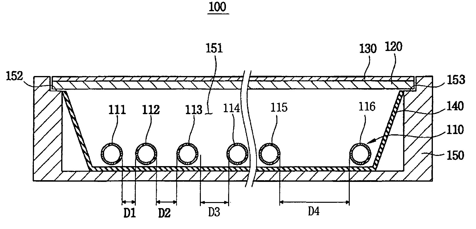
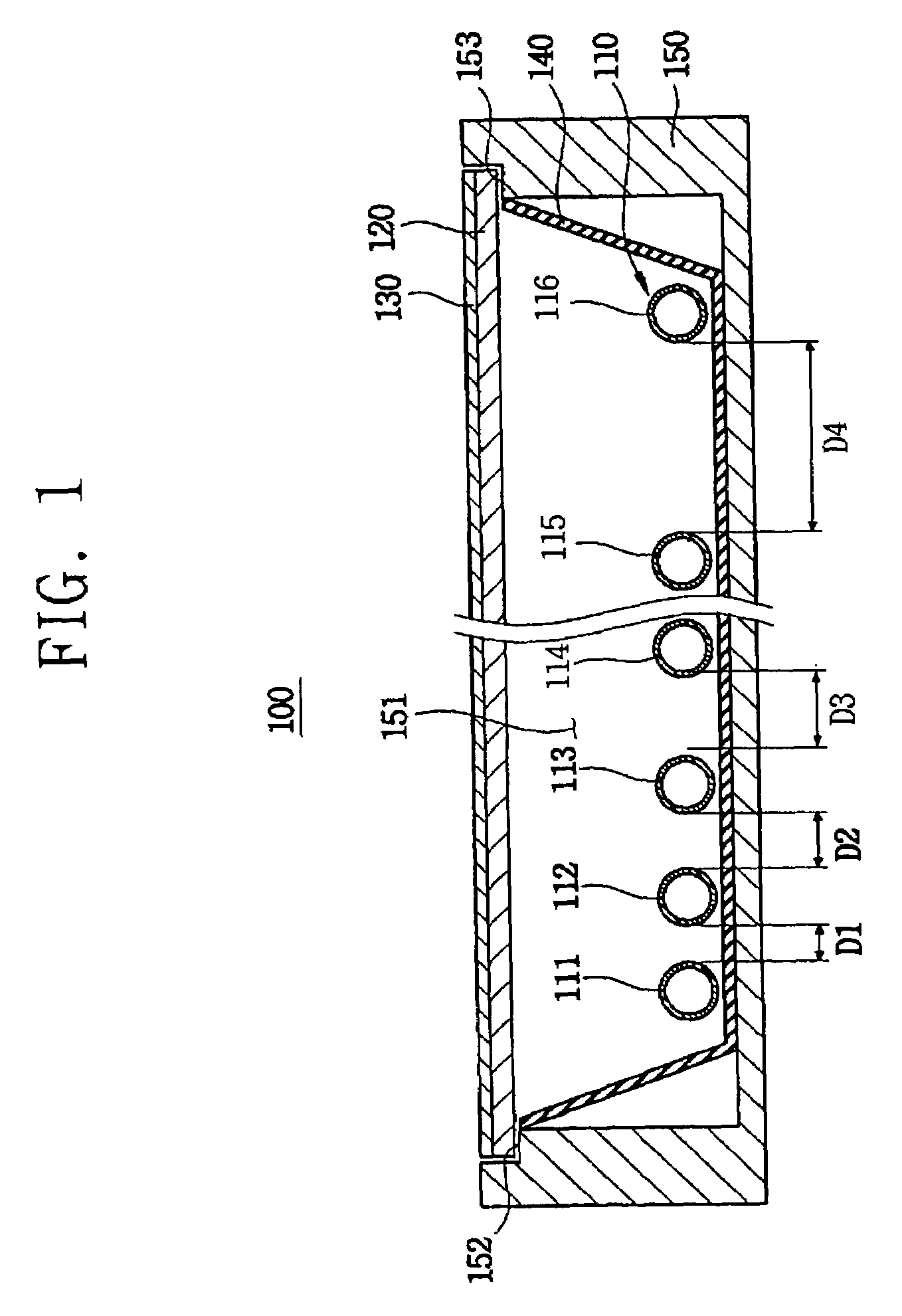
[0040]FIG. 1 is a cross-sectional view showing a backlight assembly according to a first exemplary embodiment of the present invention.

[0041]Referring to FIG. 1, a backlight assembly 100 according to a first exemplary embodiment of the present invention includes a plurality of lamps 110 that emits a first light, a diffusion plate 120 disposed on the lamps 110 to diffuse the first light, an optical sheet 130 disposed on the diffusion plate 120 to collect the light from the diffusion plate 120, a reflection plate 140 disposed under the lamps 110 to reflect the first light to the diffusion plate 120, and a receiving container 150 that provides a receiving container 150 so as to successively receive the reflection plate 140, the lamps 110, the diffusion plate 120 and the optical sheet 130.

[0042]In order to provide the receiving space 151, the receiving container 150 includes a bottom surface and a sidewall extended to a direction substantially perpendicular to the ...

embodiment 2

[0062

[0063]FIG. 3 is a plane view showing a backlight assembly according to a second exemplary embodiment of the present invention. FIG. 4 is a cross-sectional view taken along the line I–I′ of FIG. 3. In FIGS. 3 and 4, the same reference numerals denote the same elements in FIG. 1, and thus the detailed descriptions of the same elements will be omitted.

[0064]Referring to FIGS. 3 and 4, a backlight assembly 200 includes a receiving container 150, a reflection plate 140, a plurality of lamps 210, a diffusion plate 120 and an optical sheet 130.

[0065]The reflection plate 140 is received into a receiving space 151 of the receiving container 150, and the lamps 210 are disposed on the reflection plate 140. The lamps 210 are spaced apart from each other by a substantially identical interval. The lamps 210 include a first lamp 211, a second lamp 212, a third lamp 213 and a fourth lamp 214. Number of the lamps 210 may increase or decrease depending upon a size of a liquid crystal display pan...

embodiment 3

[0073

[0074]FIG. 5 is a graph showing a brightness distribution in accordance with an amount of a discharge gas injected into the lamps shown in FIG. 3.

[0075]In this exemplary embodiment, a backlight assembly 200 includes a receiving container 150 providing a receiving space 151, a reflection plate 140 received into the receiving space 151, first to fourth lamps 211, 212, 213 and 214 disposed on a bottom surface of the reflection plate 140, a diffusion plate 120 disposed on the first to fourth lamps 211, 212, 213 and 214 and an optical sheet 130 disposed on the diffusion plate 120. In FIG. 5, the same reference numerals denote the same elements in FIG. 1, and thus the detailed descriptions of the same elements will be omitted. The first to fourth lamps 211, 212, 213 and 214 are disposed on the bottom surface of the reflection plate 140, and spaced apart from each other by a substantially identical interval between the lamps. The first lamp 211 is disposed at a position adjacent to a ...


PUM

PropertyMeasurementUnit
tube currentaaaaaaaaaa
currentaaaaaaaaaa
inner pressures P1aaaaaaaaaa

Abstract

In a backlight assembly and a liquid crystal display apparatus, a plurality of lamps disposed in a receiving space of the backlight assembly is spaced apart from each other by various intervals between the lamps depending upon positions at which the lamps are disposed. Each of the lamps may also have an external electrode having a different area from each other or due to the positions at which the lamps are disposed. Furthermore, each of the lamps may have a different amount of discharge gas injected thereinto due to the positions at which the lamps are disposed. Accordingly, the liquid crystal display apparatus may provide a uniform brightness, and prevent deterioration of display quality thereof.

Description

CROSS-REFERENCE TO RELATED APPLICATION[0001]This application relies for priority upon Korean Patent Application No. 2003-35107 filed on May 31, 2003, the contents of which are herein incorporated by reference in its entirety.BACKGROUND OF THE INVENTION[0002]1. Field of the Invention[0003]The present invention relates to a backlight assembly and a liquid crystal display apparatus having the backlight assembly. More particularly, the present invention relates to a backlight assembly capable of improving image display quality and a liquid crystal display apparatus having the backlight assembly.[0004]2. Description of the Related Art[0005]In general, a liquid crystal display apparatus displays an image using optical properties of liquid crystal. In order to display the image, the liquid crystal display apparatus includes a liquid crystal display panel on which the image is displayed and a backlight assembly that provides light to the liquid crystal display panel.[0006]A backlight assemb...

Claims


Application Information

Patent Timeline
Patent Type & Authority Patents(United States)
IPC IPC(8): F21V21/00G02F1/13357
CPCG02F1/133604G02F1/1335
Inventor YOO, HYEONG-SUKKIM, JOONG-HYUNNAM, SEOK-HYUNLIM, JONG-SUNKANG, SEOCK-HWANBYUN, JIN-SEOB
Owner SAMSUNG DISPLAY CO LTD
Why Eureka
Try Eureka