Radiator tank fastening system

a radiator and tank technology, applied in the direction of heat exchanger casings, reinforcing means, lighting and heating apparatus, etc., can solve the problems of increasing increasing the risk of bulging and eventual rupture, and requiring larger tanks, so as to improve the sealing tightness increase the thickness of the tank wall, and save costs over other designs.

Inactive Publication Date: 2018-07-24
ENTEREX AMERICA
View PDF22 Cites 1 Cited by
  • Summary
  • Abstract
  • Description
  • Claims
  • Application Information

AI Technical Summary

Benefits of technology

[0009]It is another object of the present invention to provide a system for fastening and retaining plastic tanks to heavy duty radiator cores which assures structural integrity and seal tightness without significantly increasing tank wall thickness.
[0010]A further object of the invention is to provide an improved system for fastening radiator tanks which allows the use of plastic tanks on large radiators, resulting in a cost savings over other designs.
[0011]It is yet another object of the present invention to provide an improved system for fastening and retaining plastic tanks to heavy duty radiator cores which provides force, in addition to that of crimped header tabs, to secure and seal a plastic tank to a radiator core header.
[0012]It is still yet another object of the present invention to provide a system for fastening plastic tanks to large radiator cores which provides restraint against bulging of the tank top and side walls under internal pressure.
[0013]It is still yet another object of the present invention to provide a system for fastening radiator tanks which provides a means in the field to increase gasket compression to eliminate a leak.
[0015]The above and other objects, which will be apparent to those skilled in the art, are achieved in the present invention which is directed to a heat exchanger manifold, comprising a heat exchanger header having a header plate with a periphery, a plurality of tube openings within the header plate portion periphery adapted to connect to tubes of a heat exchanger core, a groove around the periphery of the header plate to receive a foot of a tank, and a fastener base extending inward from the header plate. The manifold further comprises a heat exchanger tank having an opening for mating with the header, a foot extending substantially around a periphery of the opening which is received in the header groove, and a fastener base extending from an inner surface of the tank. A resilient sealing gasket is positioned between the tank foot and the header groove to seal the tank to the header, and a plurality of tabs extending around the periphery of the header are crimped over the tank foot to make the seal between the header groove and the tank foot. A fastener secured between the header plate fastener base and the tank fastener base restricts movement of the tank away from the header during operation to maintain the seal between the header groove and the tank foot.

Problems solved by technology

Heavy duty radiators are usually larger than automobile radiators, consequently requiring larger tanks.
In addition, as radiator tanks become larger, they become more susceptible to bulging and eventual rupture as a result of internal pressure.

Method used


Image

  • Radiator tank fastening system
  • Radiator tank fastening system
  • Radiator tank fastening system

Examples


Embodiment Construction

)

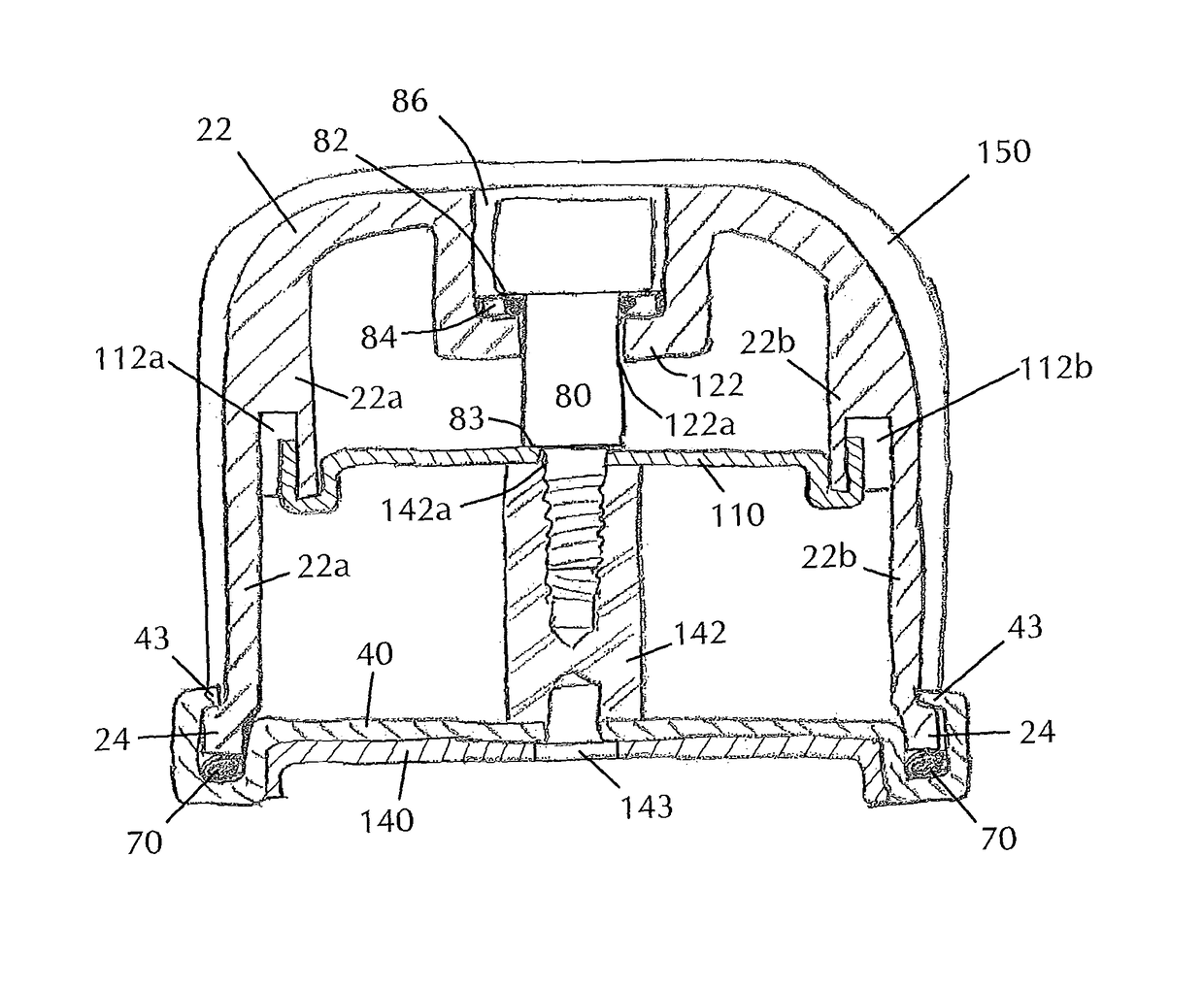
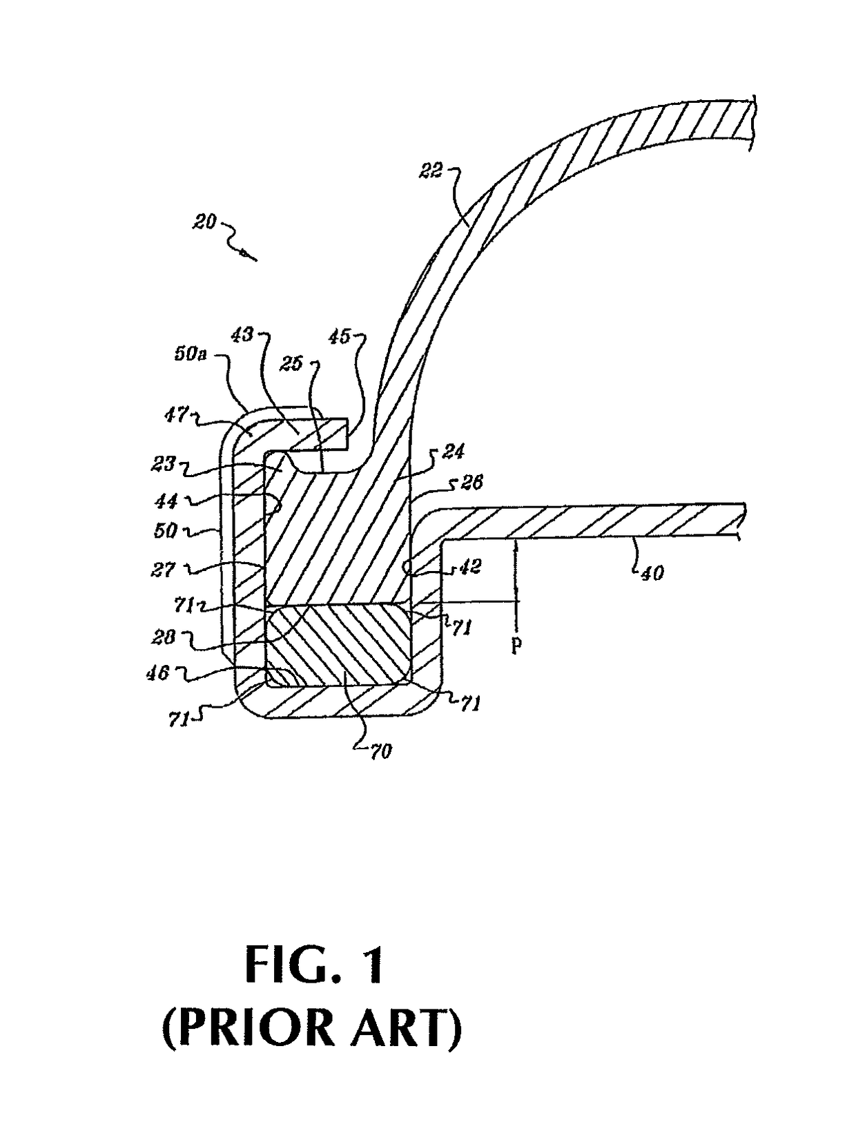
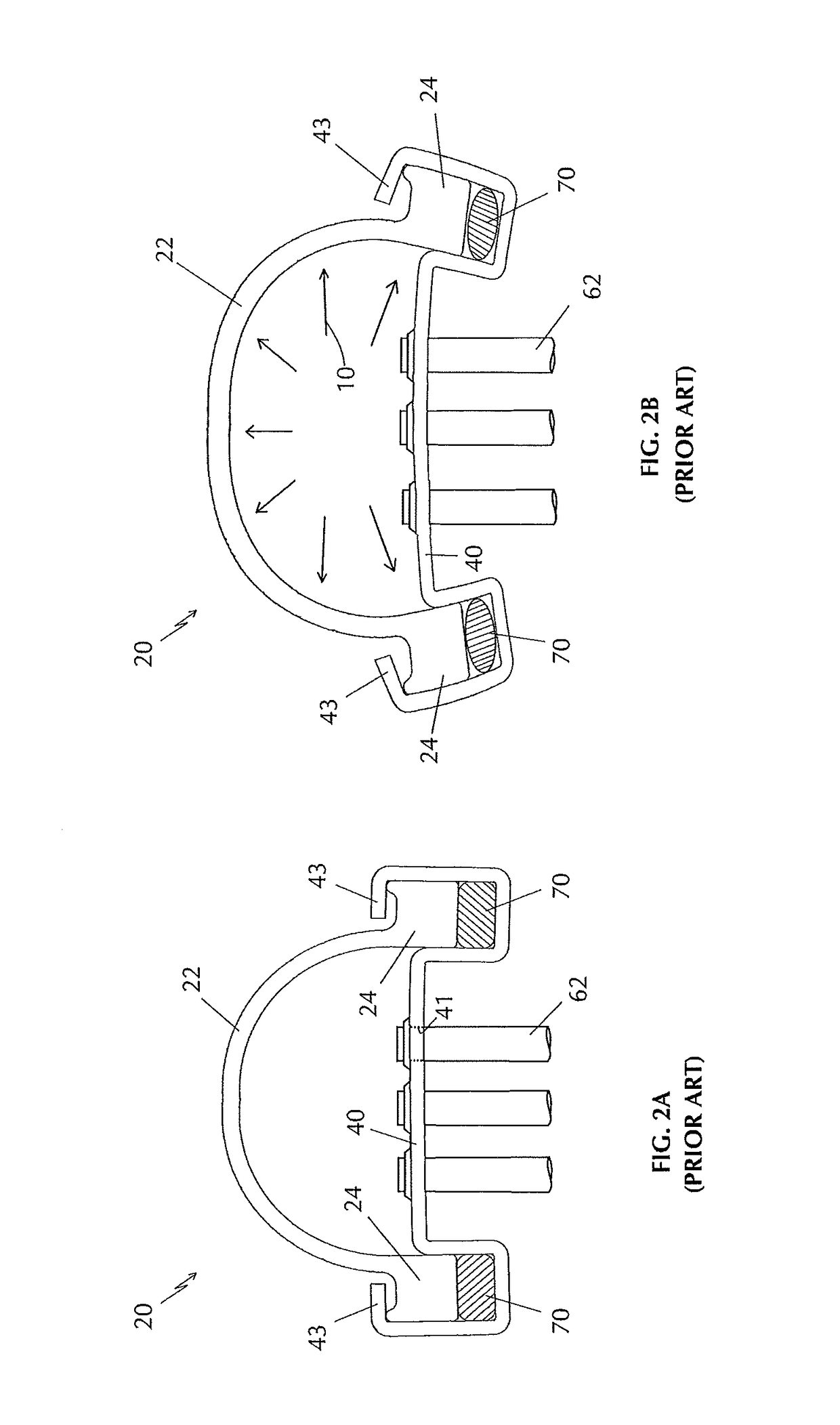
[0034]In describing the embodiments of the present invention, reference will be made herein to FIGS. 1-5 of the drawings in which like numerals refer to like features of the invention.

[0035]As used herein, a heat exchanger manifold consists of an inlet or outlet tank for passage of the heat exchanger coolant, a header for attachment to the tubes of a heat exchanger core, and a seal between the tank and header. Typically, the tank may be made of an otherwise conventional molded plastic such as glass-reinforced Nylon 6 / 6 material, and the header may be made of a metal such as aluminum. Other types of tank and header materials may also be employed. The radiator tank fastening system of the present invention may be used in heavy-duty truck or other motor vehicle heat exchangers and in some construction and industrial equipment, such as in large air compressors and diesel electric generators, or in other heat exchanger applications where strength, vibration resistance and long life are ...


PUM

PropertyMeasurementUnit
pressureaaaaaaaaaa
lengthaaaaaaaaaa
forcesaaaaaaaaaa

Abstract

A heat exchanger manifold comprises a heat exchanger header having a header plate with a periphery, a plurality of tube openings within the header plate portion periphery adapted to connect to tubes of a heat exchanger core, a groove around the periphery of the header plate to receive a foot of a tank, and a fastener base extending inward from the header plate. The manifold includes a heat exchanger tank having an opening for mating with the header, a foot extending substantially around a periphery of the opening which is received in the header groove, and a fastener base extending from an inner surface of the tank. A resilient sealing gasket is positioned between the tank foot and the header groove to seal the tank to the header, and a plurality of tabs extending around the periphery of the header are crimped over the tank foot to make the seal between the header groove and the tank foot. During operation, a fastener between the header plate fastener base and the tank fastener base restricts movement of the tank away from the header to maintain compression on the seal between the header groove and the tank foot, and a cross tie extending between interior surfaces of the tank side walls restricts movement of the tank side walls away from each other.

Description

RELATED APPLICATIONS[0001]This application claims priority to U.S. Patent Application No. 62 / 061,736, filed on Oct. 9, 2014.BACKGROUND OF THE INVENTION[0002]1. Field of the Invention[0003]The present invention relates to engine cooling radiators and, more particularly, to heavy duty radiator cores such as for large air compressors, diesel electric generators, and some construction and industrial equipment, which utilize plastic tanks.[0004]2. Description of Related Art[0005]Inlet and outlet tanks for engine cooling radiators have become increasingly designed as ribbed plastic moldings, usually injection molded of Nylon 6-6. This is almost universally true for tanks for automobile radiators, as the use of brazed aluminum radiator cores with plastic tanks has been found to provide significant cost savings over older designs using copper / brass cores with soldered drawn brass tanks. As might be expected, the quest for cost savings has caused the application of plastic tanks to spread to...

Claims


Application Information

Patent Timeline
Patent Type & Authority Patents(United States)
IPC IPC(8): F28F21/06F28F9/02F28D21/00
CPCF28F21/067F28F9/0226F28D2021/0031F28F2275/205F28F2009/0292F28F2225/08F28F2275/20F28F9/0229
Inventor MCWAIN, LYMAN J.
Owner ENTEREX AMERICA
Why Eureka
Try Eureka