Image forming apparatus with printer unit and air-cooled reader unit

a technology of image forming apparatus and reader unit, which is applied in the direction of electrographic process apparatus, instruments, optics, etc., can solve the problems of thermal expansion, reducing the level of accuracy at which the image sensor can read an original, and not cooling the image sensor across the entire range in terms of the primary scan direction of the image reading apparatus

Active Publication Date: 2018-09-11
CANON KK
View PDF10 Cites 1 Cited by
  • Summary
  • Abstract
  • Description
  • Claims
  • Application Information

AI Technical Summary

Benefits of technology

[0006]The present invention was made in consideration of the current state of the structural arrangement for an image reading apparatus described above. Thus, the primary object of the present invention is to provide an image reading apparatus which is capable of preventing its image reading means from becoming nonuniform in temperature in terms of its primary scan direction.

Problems solved by technology

That is, as the image sensor of the apparatus increases in temperature, it thermally expands, reducing therefore in the level of accuracy at which it can read an original.
However, in the case of the structural arrangement disclosed in Japanese Patent No. 5570490, the image sensor is not cooled across its entire range in terms of the primary scan direction of the image reading apparatus.
Therefore, it is likely to become nonuniform in the amount of thermal expansion in terms of its primary scan direction.
If it becomes nonuniform in the amount of thermal expansion, it is possible that the image reading apparatus will reduce in accuracy due to the blurring attributable to the nonuniform expansion of an original and / or focal nonuniformity of the image sensor.
That is, it is possible that the structural arrangement disclosed in Japanese Patent Application No. 5570490 will reduce an image reading apparatus in accuracy.

Method used


Image

  • Image forming apparatus with printer unit and air-cooled reader unit
  • Image forming apparatus with printer unit and air-cooled reader unit
  • Image forming apparatus with printer unit and air-cooled reader unit

Examples


embodiment 1

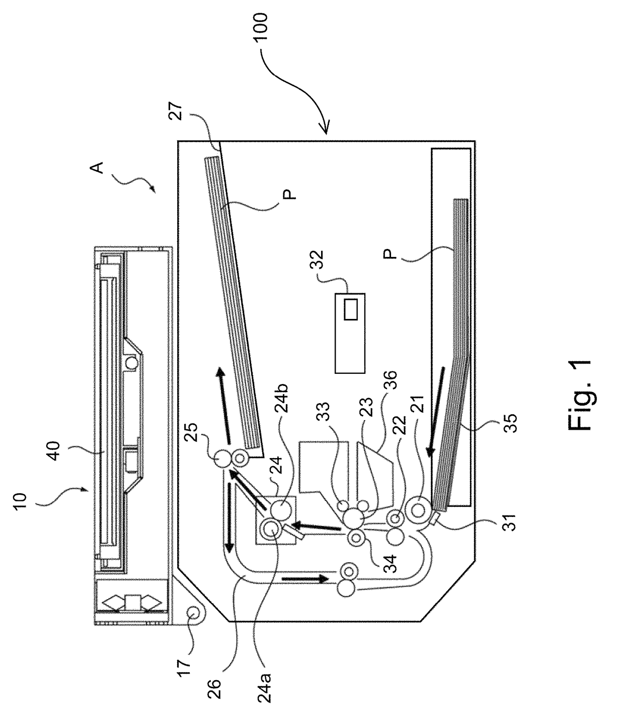
[0015]To begin with, an image forming apparatus A equipped with an image reading portion 10 (reader unit) in this embodiment is described about its overall structure, along with its image forming operation, with reference to the appended drawings. By the way, this embodiment is not intended to limit the present invention in scope in terms of the shapes of structural components of the image forming apparatus and the image reading portion, their positional relationship, and the like, unless specifically noted.

[0016]The image forming apparatus A is equipped with on the image reading portion 10 (reader unit) which reads an original, and a printer unit 100 which forms a toner image on a sheet of recording medium.

[0017]Referring to FIG. 1, the printer unit 100 has a photosensitive drum 23 (image bearing member), a charge roller 33, an exposing apparatus 32, a developing apparatus 36, a transfer roller 34, and the like.

[0018]The aforementioned image reading portion 10 (reader unit) functio...

embodiment 2

[0044]Next, the image forming apparatus A equipped with the image reading portion 10 in the second embodiment of the present invention is described with reference to the drawings. The portions of the image reading portion 10 and its image reading apparatus, the description of which will be the same as that of the counterparts in the first embodiment, are given the same referential codes as those given to the counterparts in FIGS. 1-3, and are not described here.

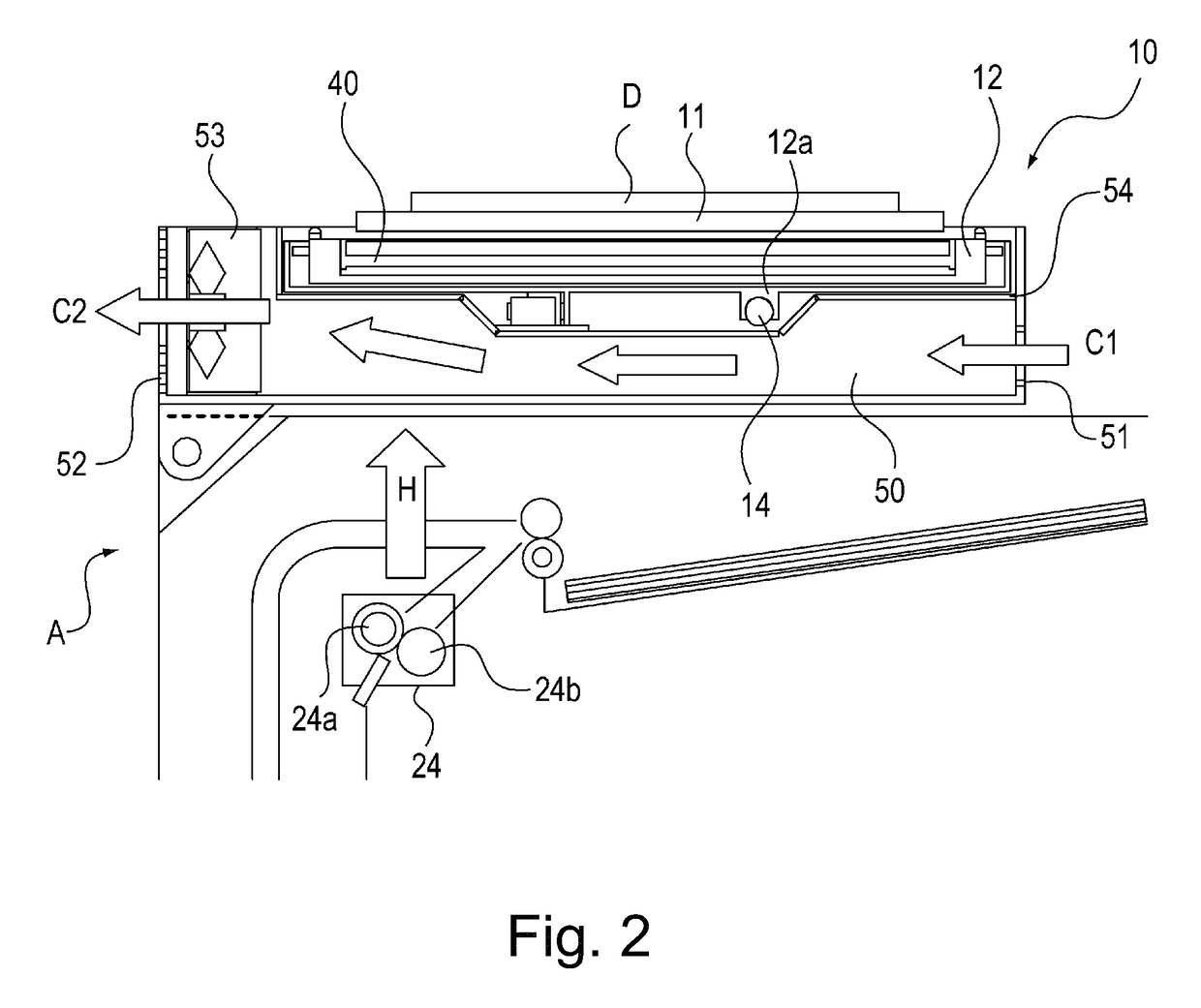
[0045]FIG. 4 is a schematic sectional view of the image reading portion 10 in this embodiment, and its adjacencies, when the image reading portion 10 is closed. FIG. 5 is a schematic sectional view of the image reading portion 10 in this embodiment, and its adjacencies, when the image reading portion 10 is open.

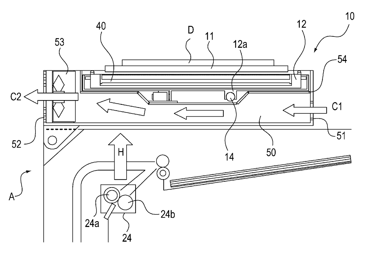
[0046]Referring to FIGS. 4 and 5, the image reading portion 10 in this embodiment is provided with an air intake opening 51, which is for taking the ambient air into the image reading portion 10 in the direction indica...


PUM


Abstract

An image forming apparatus includes a printer unit configured to form a toner image on a recording material, the printer unit including a fixing portion configured to heat-fix the toner image on the recording material; a reader unit provided above the printer unit and configured to read an image of an original, the reader unit including an image sensor configured to optically read the original; wherein in a side of the reader unit opposed to the printer unit, there are provided a suction opening configured to suck air from an outside of the reader unit and a discharging opening configured to discharge the air to an outside of the reader unit, and wherein an air flow path connecting the suction opening and the discharging opening overlaps with an entirety of the image sensor in a main scan direction which is an axial direction of the image sensor.

Description

FIELD OF THE INVENTION AND RELATED ART[0001]The present invention relates to an image reading apparatus which is suitable for an image forming apparatus. Further, it relates to an image forming apparatus such as an electrophotographic copying machine, an electrophotographic printer (laser beam printer, and LED printer, for example), a facsimileing machine, and the like.[0002]In the field of an image reading apparatus, there has been known an apparatus equipped with an image sensor (image reading means) which is structured so that it reads an original by outputting a beam of light (laser light) in a manner to illuminate an original with the beam, and catching the light reflected by the original; it obtains the data of an original, as data of a preset number of linear pieces of the original, which are parallel to the direction in which the original is scanned. Further, there has been known an image forming apparatus equipped with an image reading apparatus such as the one described ab...

Claims


Application Information

Patent Timeline
Patent Type & Authority Patents(United States)
IPC IPC(8): G03G15/00G03G15/20H04N1/00G03G21/20
CPCG03G21/206G03G15/2028H04N1/00795H04N1/00615H04N1/00602
Inventor ASANO, FUMIO
Owner CANON KK
Why Eureka
Try Eureka