
Game camera mounting system
a game camera and mounting system technology, applied in the direction of screws, threaded fasteners, instruments, etc., can solve the problems of game camera theft and serious problem of game camera theft, and achieve the effect of easily adjusted to the desired viewing angl
- Summary
- Abstract
- Description
- Claims
- Application Information
AI Technical Summary
Benefits of technology
Problems solved by technology
Method used
Image

Examples
Embodiment Construction
[0040]The present invention and the various features and advantageous details thereof are explained more fully with reference to the non-limiting embodiments described in detail in the following description.
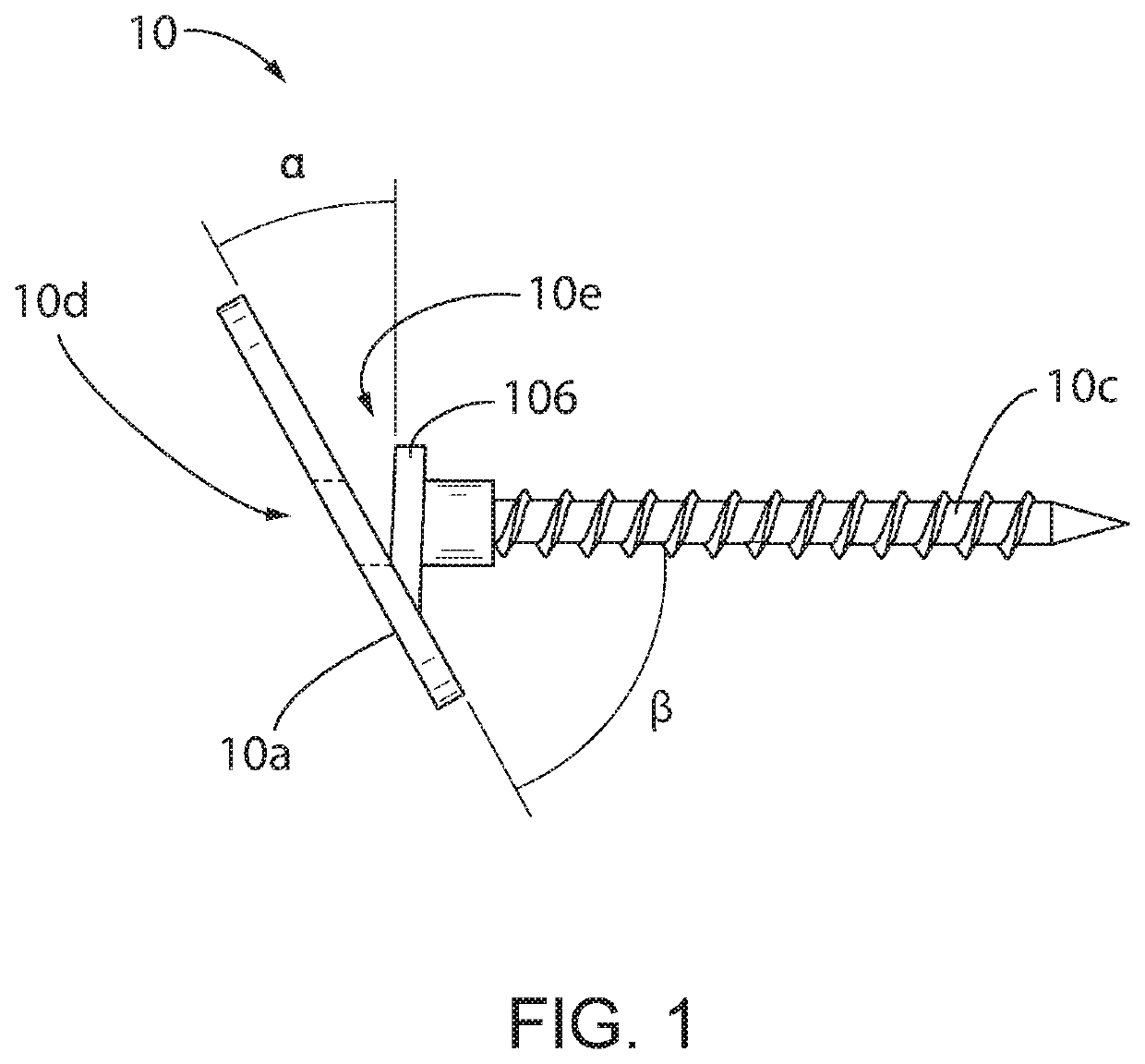
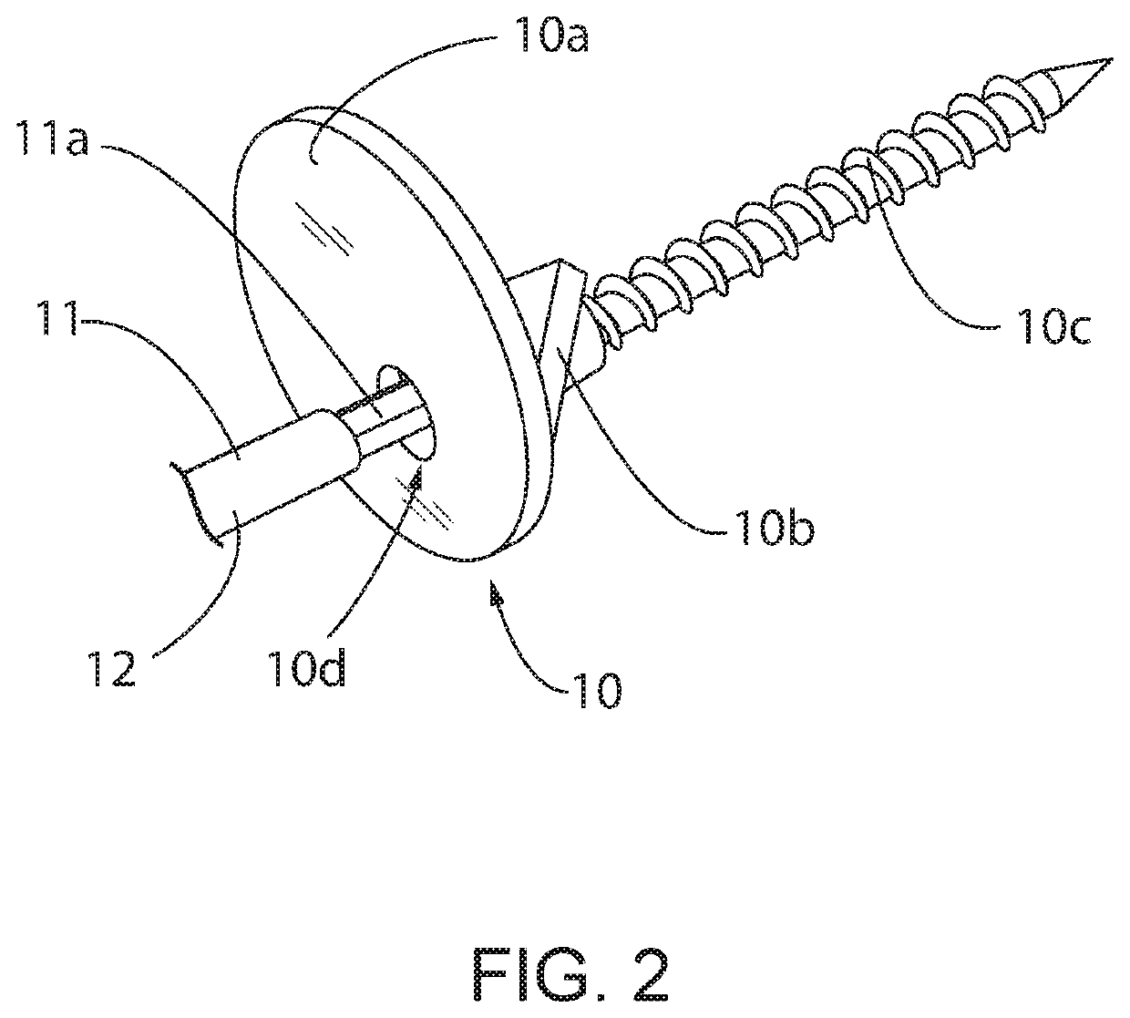
[0041]Referring first to FIG. 1, a mount 10 of a camera mounting system 9 is shown according to an embodiment of the invention. The mount 10 includes a plate 10a, a tab 10b, and a screw 10c. In the representative embodiment of the invention, the tab 10b is permanently coupled to the plate 10a. For example, an edge of the tab 10b may be welded to a surface of the tab 10b. As shown in FIG. 1, the tab 10b may be oriented at an angle α from the plate 10a. While FIG. 1 depicts the angle α as being 30 degrees, it is contemplated that the plate 10a and tab 10b may be oriented at any angle with respect to each other. Further, the plate 10a and tab 10b each include an orifice 10d, 10e, respectively.
[0042]The screw 10c is inserted through the orifice 10e of the tab 10b, so that the head of...
PUM
 Abstract
Description
Claims
Application Information