Method for counting revolutions of a wheel

a technology of revolutions and counting methods, applied in the field of counting revolutions of wheels, can solve the problems of multiple constraints on the warping of the wheel, and the failure of the counter unit of the counter device, so as to increase the cost or complexity of the operation, and improve the accuracy of the revolutions. the effect of the accuracy

Active Publication Date: 2020-03-17
SAGEMCOM ENERGY & TELECOM
View PDF5 Cites 0 Cited by
  • Summary
  • Abstract
  • Description
  • Claims
  • Application Information

AI Technical Summary

Benefits of technology

[0012]An object of the invention is to improve the accuracy with which revolutions of a wheel are counted, but without that significantly increasing the cost or the complexity of performing said counting.SUMMARY OF THE INVENTION
[0018]Detecting disturbances that might affect detection of the target makes it possible to correct the number of pulses obtained during such disturbances and thus to improve detection of the target and counting accuracy.
[0019]The counting method of the invention thus improves counting accuracy by correcting the effect of the disturbances by analyzing data that is available (the values of the differential pulses), and it does not require additional hardware components to be added in order to improve the accuracy of target detection. The complexity and the cost of performing the counting method of the invention are thus reduced.

Problems solved by technology

Unfortunately, the gas meter wheel and the target detector device are subjected to multiple constraints that tend to disturb counting: mechanical drift, e.g. due to vibration, to wear phenomena causing the wheel to warp, to components aging, to temperature variations, etc.
The counter unit of the counter device is also subjected to multiple constraints.
The electrical components of the counter unit are in particular subjected to radiofrequency disturbances and to disturbances on the power supply.
Radiofrequency disturbances result in particular from radio waves being transmitted by the gas meter or in the environment of the gas meter in order to transmit data by wireless communication.
Power supply disturbances result in particular from transient inrush currents that can occur each time the counter unit starts (since it is kept on standby for most of the time), where such an inrush current causes a drop in the power supply voltage that is of short duration, but relatively significant.
These constraints and disturbances together tend to reduce the counting accuracy.

Method used


Image

  • Method for counting revolutions of a wheel
  • Method for counting revolutions of a wheel
  • Method for counting revolutions of a wheel

Examples


Embodiment Construction

[0028]The invention is described below in application to a gas meter for installing in a private building for connecting a gas distribution installation in the building to an external gas distribution network. Naturally, the invention is not limited to this particular application, and in particular it also applies to meters for water, electricity, . . . .

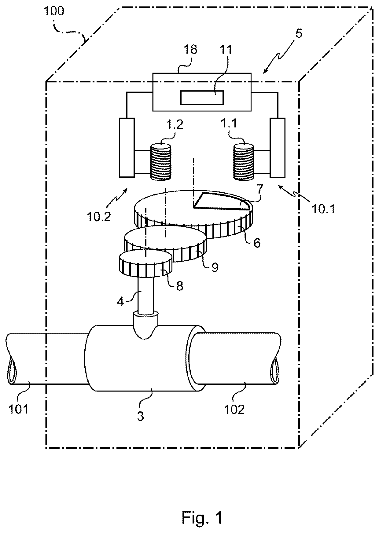
[0029]With reference to FIGS. 1 to 5, the gas meter comprises a structure forming a box 100 at which there arrives a gas feed pipe 101 that is connected to the external distribution network, and from which there leaves a pipe 102 of the gas distribution installation. The two pipes are connected together by a coupling 3 in which there extends a portion of a rotary element 4 that is driven in rotation by the gas flowing through the coupling from the pipe 101 towards the pipe 102 in such a manner that rotation of the rotary element 4 is representative of the quantity of gas passing through the coupling 3.

[0030]A wheel 6 made of non-met...


PUM


Abstract

The invention relates to a method for counting revolutions of a wheel (6) to which a target (7) is attached, the counting method comprising the step of: generating an oscillating signal representing the presence or the absence of the target (7); comparing an amplitude of the signal with a voltage threshold in order to obtain pulses (19); and detecting the presence of the target (7) or the absence of the target on the basis of the number of pulses obtained. The method also comprises a step of detecting a disruption which is implemented as feedback and which consists in acquiring differential pulse values each equal to a difference between two numbers of pulses obtained during two consecutive detection intervals, and in detecting a disruption upon identifying an erroneous sequence of consecutive differential pulses. A consumption meter and a computer program corresponding to the method and means for storing such a program are also claimed.

Description

[0001]The present invention relates to counting revolutions of a wheel, e.g. in the field of mechanical meters such as those used for distributing gas or water.BACKGROUND OF THE INVENTION[0002]A gas meter is known that has a wheel rotating about an axis relative to a structure in such a manner that the speed of rotation of the wheel is representative of the quantity of gas distributed.[0003]The gas meter has a device for counting the number of revolutions of the wheel. The counter device comprises a target, a target detector device, and a counter unit.[0004]A counter device is thus known in which the target is an off-center magnet fastened to the wheel, and in which the detector device comprises a magnetic relay of the reed bulb type that is mounted stationary relative to the structure. The counter unit is connected to the magnetic relay in order to detect the passage of the magnet and thus count the number of revolutions.[0005]A counter device is also known in which the target is a...

Claims


Application Information

Patent Timeline
Patent Type & Authority Patents(United States)
IPC IPC(8): G01B7/30G01D11/24G01D5/12G01R33/00G01R33/09G01D5/244G01D5/20G01D5/14G01B7/14G01B7/00
CPCG01D11/245G01D5/202G01D5/145G01D5/14G01R33/0023G01R33/0052G01R33/09G01D5/12G01D5/24461G01B7/30G01B7/003G01B7/14G01D4/00
Inventor TEBOULLE, HENRI
Owner SAGEMCOM ENERGY & TELECOM
Why Eureka
Try Eureka