Fixing device and image forming apparatus

a technology of fixing device and image forming apparatus, which is applied in the direction of electrographic process apparatus, instruments, optics, etc., can solve the problems of deteriorating the responsiveness of the temperature detector with respect to a temperature change in the heat source or the like, and achieves the effects of suppressing excessive temperature rise, reducing heat conduction, and reducing heat conduction

Active Publication Date: 2020-03-17
FUJIFILM BUSINESS INNOVATION CORP
View PDF7 Cites 0 Cited by
  • Summary
  • Abstract
  • Description
  • Claims
  • Application Information

AI Technical Summary

Benefits of technology

[0005]To suppress the excessive rise of the temperature in the non-sheet-passing area of a contact portion, such as a fixing belt, that comes into contact with the recording material, a fixing device includes, for example, a high-thermal-conductivity portion having a higher thermal conductivity than the contact portion and other relevant elements and provided on a side of a heat source that is opposite a side facing the contact portion. In such a fixing device, to suppress the conduction of heat generated by the heat source to the high-thermal-conductivity portion when, for example, the contact portion starts to be heated by the heat source, a low-thermal-conductivity portion having a lower thermal conductivity than the high-thermal-conductivity portion may be provided between the heat source and the high-thermal-conductivity portion.

Problems solved by technology

Consequently, the responsiveness of the temperature detector with respect to a temperature change in the heat source or the like may be deteriorated.
However, aspects of the non-limiting embodiments are not required to address the advantages described above, and aspects of the non-limiting embodiments of the present disclosure may not address advantages described above.

Method used


Image

  • Fixing device and image forming apparatus
  • Fixing device and image forming apparatus
  • Fixing device and image forming apparatus

Examples


exemplary embodiment 1

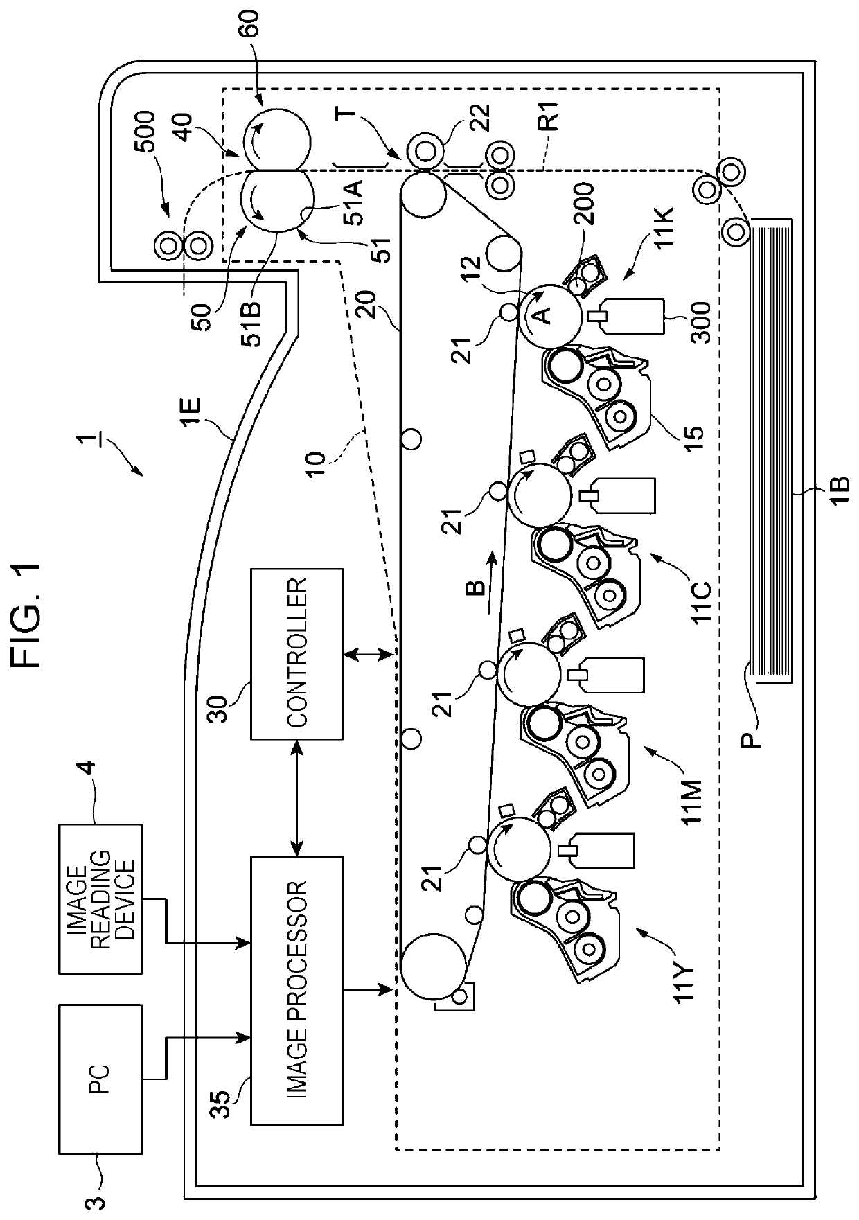
[0024]FIG. 1 illustrates an overall configuration of an image forming apparatus 1.

[0025]The image forming apparatus1 is a so-called tandem-type color printer.

[0026]The image forming apparatus 1 includes an image forming section 10 as an exemplary image forming device. The image forming section 10 forms an image on a sheet P as an exemplary recording material in accordance with pieces of image data for different colors.

[0027]The image forming apparatus 1 further includes a controller 30 and an image processor 35.

[0028]The controller 30 controls relevant functional elements included in the image forming apparatus 1.

[0029]The image processor 35 processes the pieces of image data received from a device such as a personal computer (PC) 3 or an image reading device 4.

[0030]The image forming section 10 includes four image forming units 11Y, 11M, 11C, and 11K (hereinafter also generally denoted as “image forming units 11”) arranged at intervals and in parallel.

[0031]The image forming units ...

second exemplary embodiment

[0114]A second exemplary embodiment of the present disclosure will now be described. Elements that are the same as those described in the first exemplary embodiment are denoted by corresponding ones of the reference numerals, and detailed description of those elements is omitted herein.

[0115]FIGS. 7 and 8 illustrate an arrangement of the heat source 52, the high-thermal-conductivity portion 53, the low-thermal-conductivity portion 56, and the temperature sensors 57 according to the second exemplary embodiment. FIG. 7 is a plan view of the heat source 52, the high-thermal-conductivity portion 53, the low-thermal-conductivity portion 56, and the temperature sensors 57 seen in the direction of stacking of the high-thermal-conductivity portion 53 and so forth on the heat source 52. FIG. 8 is a sectional view of a width-direction central portion of the fixing device 40, taken along line VIII-VIII illustrated in FIG. 7.

[0116]In FIG. 7, the base layer 521 of the heat source 52 is not illus...

third exemplary embodiment

[0128]A third exemplary embodiment of the present disclosure will now be described. Elements that are the same as those described in the first exemplary embodiment are denoted by corresponding ones of the reference numerals, and detailed description of those elements is omitted herein.

[0129]FIGS. 9 and 10 illustrate an arrangement of the heat source 52, the high-thermal-conductivity portion 53, the low-thermal-conductivity portion 56, and the temperature sensors 57 according to the third exemplary embodiment. FIG. 9 is a plan view of the heat source 52, the high-thermal-conductivity portion 53, the low-thermal-conductivity portion 56, and the temperature sensors 57 seen in the direction of stacking of the high-thermal-conductivity portion 53 and so forth on the heat source 52. FIG. 10 is a sectional view of a width-direction central portion of the fixing device 40, taken along line X-X illustrated in FIG. 9.

[0130]In FIG. 9, the base layer 521 of the heat source 52 is not illustrated...


PUM

PropertyMeasurementUnit
thermal-conductivityaaaaaaaaaa
thermal conductivityaaaaaaaaaa
temperatureaaaaaaaaaa

Abstract

A fixing device includes a contact portion that comes into contact with a recording material transported; a heat source that heats the contact portion and has a counter surface and an opposite surface, the counter surface facing the contact portion; a high-thermal-conductivity portion provided on the opposite surface of the heat source and extending in a width direction intersecting a transport direction of the recording material, the high-thermal-conductivity portion having a higher thermal conductivity than the contact portion; a low-thermal-conductivity portion provided between the opposite surface of the heat source and the high-thermal-conductivity portion and having a lower thermal conductivity than the high-thermal-conductivity portion; and a temperature detector that detects a temperature of the heat source and is provided on the opposite surface of the heat source and at a position shifted from the high-thermal-conductivity portion and the low-thermal-conductivity portion in the transport direction.

Description

CROSS-REFERENCE TO RELATED APPLICATIONS[0001]This application is based on and claims priority under 35 USC 119 from Japanese Patent Application No. 2018-176442 filed Sep. 20, 2018.BACKGROUND(i) Technical Field[0002]The present disclosure relates to a fixing device and an image forming apparatus.(ii) Related Art[0003]There is a related-art technique applied to a fixing device that includes a heater having a heat generating body provided on a heater substrate, and a heat-resisting film slidable on the heater. In this technique, the rise of the temperature of a non-sheet-passing portion is suppressed by providing a good-thermal-conductivity member on a side of the heater opposite a side of contact with the heat-resisting film and at a downstream end in a sheet passing direction (Japanese Unexamined Patent Application Publication No. 10-232576).[0004]There is another related-art technique applied to a fixing device that includes a heating member having a heat generating body provided on...

Claims


Application Information

Patent Timeline
Patent Type & Authority Patents(United States)
IPC IPC(8): G03G15/20
CPCG03G15/2039G03G15/2017G03G15/2064
Inventor KOYANAGI, KIYOSHISATO, TAKAAKIITOH, KAZUYOSHIINOUE, TORU
Owner FUJIFILM BUSINESS INNOVATION CORP
Why Eureka
Try Eureka